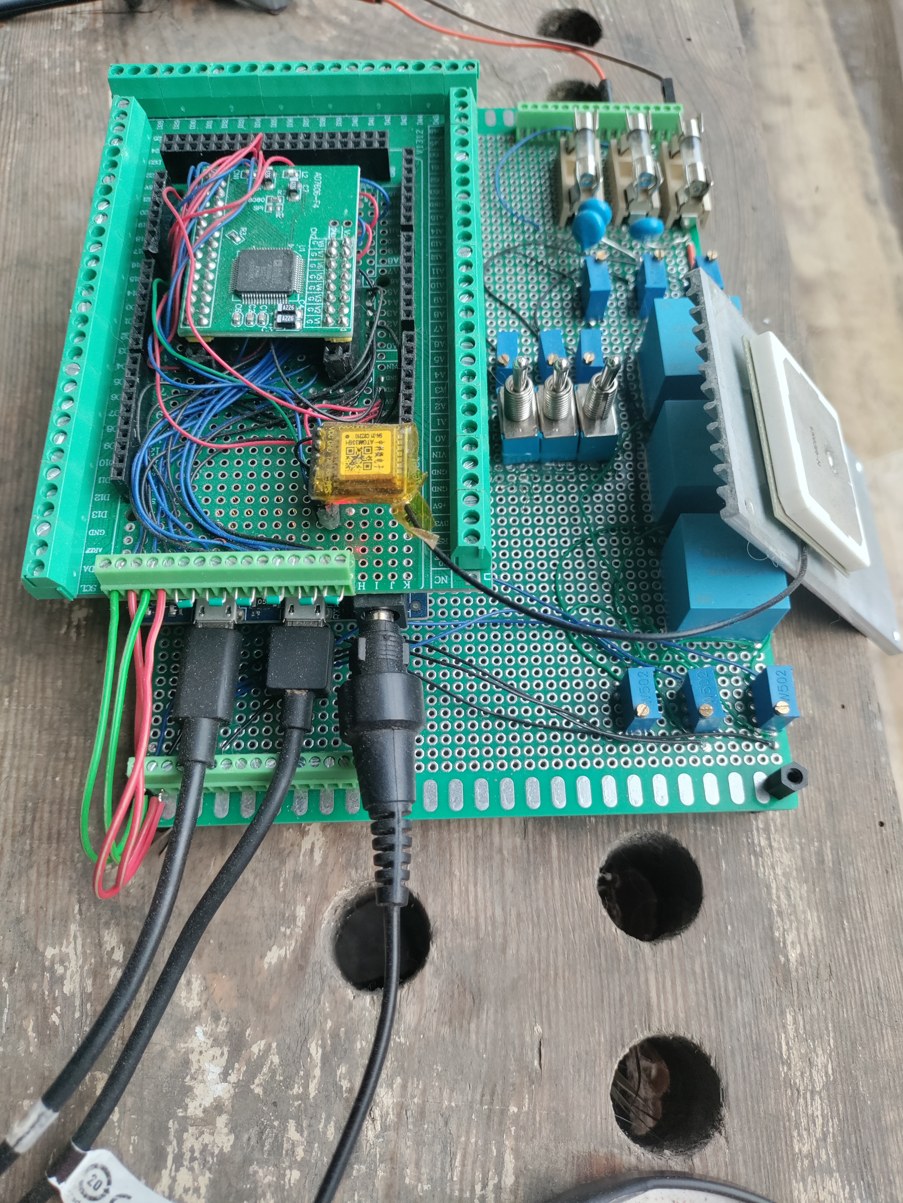
We are currently evaluating NXP’s i.MXRT1062 CPU based MCUs as the core of our PMU-001 device.
This product is advantageous as it one of the most capable MCU in terms of raw processing power, while also featuring a FPU.
Additionally, the presence of an Ethernet module with IEEE1588 ptp functionality, gives access to an adjustable free running nanoseconds timer counter with 1 sec rollover. A robust hardware on the fly correction capability allows disciplining the counter using a pps GPS signal or an ethernet based LAN ptp clock.
Note that the additional processing power has the effect of reducing IRQ contention which may introduce jitter. Faster CPU also means availability of larger PLL scales. the cycle counter has a resolution of 1/600 Mhz, while the IEEE1588 counter timer has a resolution of 40ns
As for disciplined sampling periods, the periodic interrupt timer (PIT) period can be precisely controlled with a period correction resolution of either 1/24 Mhz or 1/150 Mhz, depending on the clock source, using the LDVAL register that affects the next period, not the current period, ensuring consistent sampling.
A simple integer accumulator and integer divider method allows distribution of corrections smaller than one period correction resolution, ensuring total correction over one second brings the IEEE1588 timestamping to a disciplined second, as well as the PIT correction that ensures a true sample rate of electrical data close to nominal.
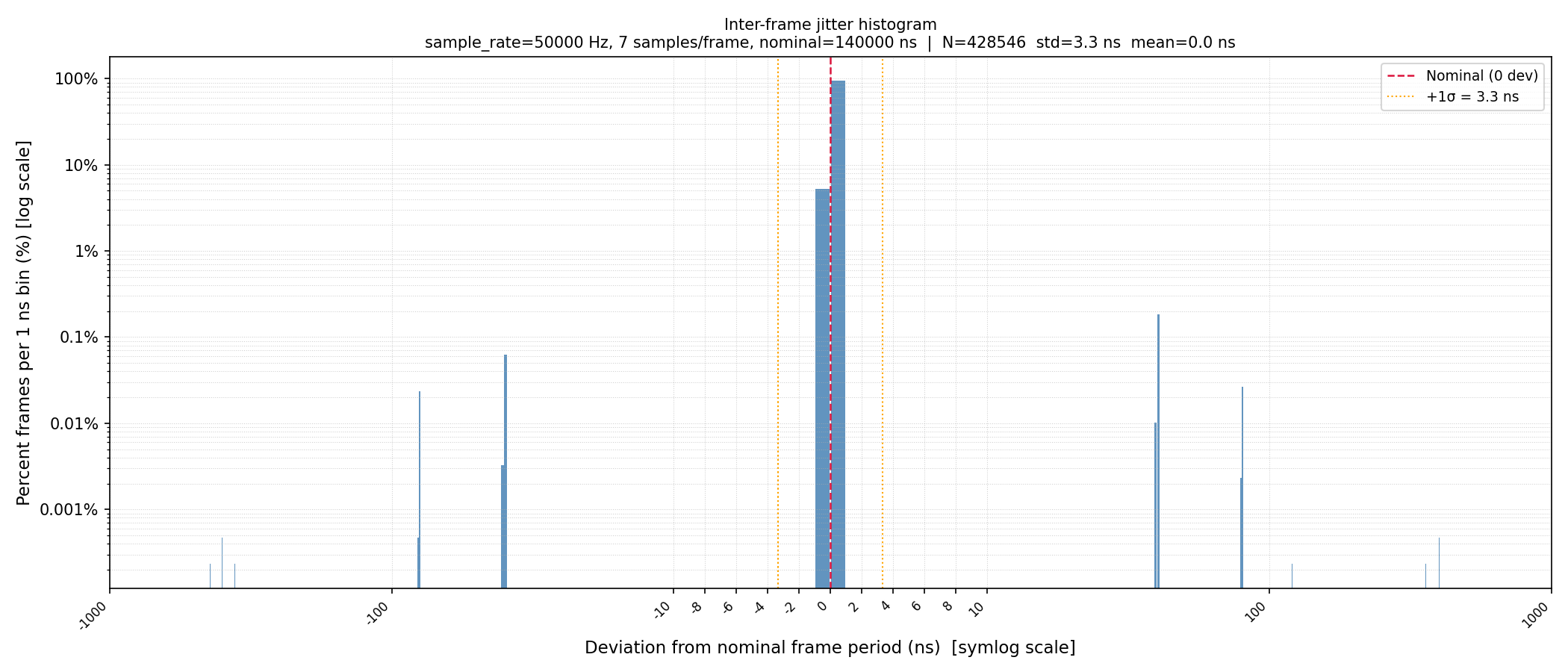
Following is the jitter analysis at 27C temperature ambient, CPU at 56C, and a 60 second recording interval of USB sample and timestamp data. No frame drops observed. The jitter analysis was performed during nominal GNSS function (no holdover).
Nominal sampling rate is 50 ksps (20 us). 8 channels recorded, 7 samples per frame, frame rate : 140 us.
symlog/log scale
As for the MCU discipline protocol : Periodic IEEE1588 timestamp timer discipline is performed every 20us sampling period, PIT timer discipline (LDVAL nominal ticks + correction) is also performed every 20us. The method used for determining the correction factor is : proportional term representing the CPU cycles phase error (absolute, not fractional error) over each pps interval, summed with an infinite integral of the residual IEEE1588 counter phase error (absolute, not fractional), also over each pps interval. Filtering of the CPU cycles phase error outliers was done by filtering out measurements above 4 sigma. The sample population maintained for average,mean and standard deviation calculations are the last 64 CPU cycles phase errors recorded (so, an history of 64 seconds)
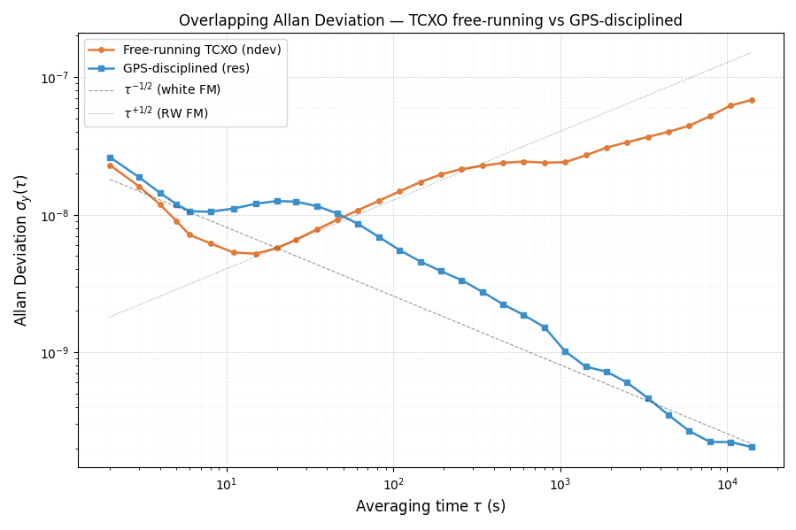
Allan Deviation chart
This is the Allan deviation calculation of the free-running CPU cycles counter, normalized to nanoseconds, and the IEEE1588 disciplined nanoseconds counter, over 41785 seconds, with a unit measurement interval tau of 1 second, while performing sampling of electrical parameters nominally at 50000 samples par second, 8 channels sampled, 7 samples * 8 channels per USB frame, and sending data over USB, but without a host listening.
We plan to perform the same measurements and Allan deviation charts without the payload calculation. Results are deemed quite satisfactory, and follow expected noise characteristics and temperature drift effects. Average temperature 45.70C @CPU, with forced convection in front of the XTAL, with CPU downstream, Average ambient temperature 25C, measurement performed at night starting at 21:30 UTC. Environment temperature is not controlled.
I will provide an updated chart with temperature data soon.
Temperature compensation
We are also evaluating an additional high precision temperature probe positioned right under the XTAL to provide ppm correction during GPS holdover intervals, with an intended goal of < 1ppm deviation during GPS holdover intervals. Such a fixture, besides providing TCXO capability without the need of replacing the onboard XTAL, also improve robustness of GPS pps signal outlier filtering, by providing ppm deviation prediction based on temperature slew, provided the temperature measurement is itself low noise. This would help identify the very infrequent but possible GPS pps glitches.
Such level of discipline precision is adequate a field microPMU, which is our intended market segment,
Discarding the requirement for an external OCXO or TCXO driven MCU or sampling timer would drastically lower R&D production, and time to market delays.
At this point in time AD7606 interfacing has been done on the new MCU platform with satisfying results.
Thus, We are now moving our development efforts towards PCB design.
For more information about i.MX-RT1060 and i.MX-RT1062 based MCUs :
Rework and Refactoring of the Host based PMU logic
We are currently in the process of updating our host based code to improve overall performance and add a substantial margin of processing time taking into account all PMU P-class and M-class modes and reporting rates, So as to deliver a product that is adequate to a large segment of cost effective and available SoC platforms, and ensuring device form factor compliance for size restricted cabinets and challenging thermal environments. This should not alter significantly the mentioned December 2026 deadline for a commercially adequate product delivery.
When it comes to switching timer modules, most designs are either based on the good old 555 timer, or some kind of 8 bit MCU that performs supervisory functions (like turning a relay off and keeping track of time), with the advantage for the later to allow for various timing and delay on/off programs. Most designs however, draw hundreds of microamperes up to several milliamperes while idling. Since one common use of these timers is to power a load for a given time in off grids setups where stored battery energy must be conserved, a low quiescent current solution would be a preferable design. Most designs are also relay based. Sturdy relays have an advantage of providing NC/NO modes natively, tolerate inductive kickback from loads such as motors, and are immune to spurious turn-ons.
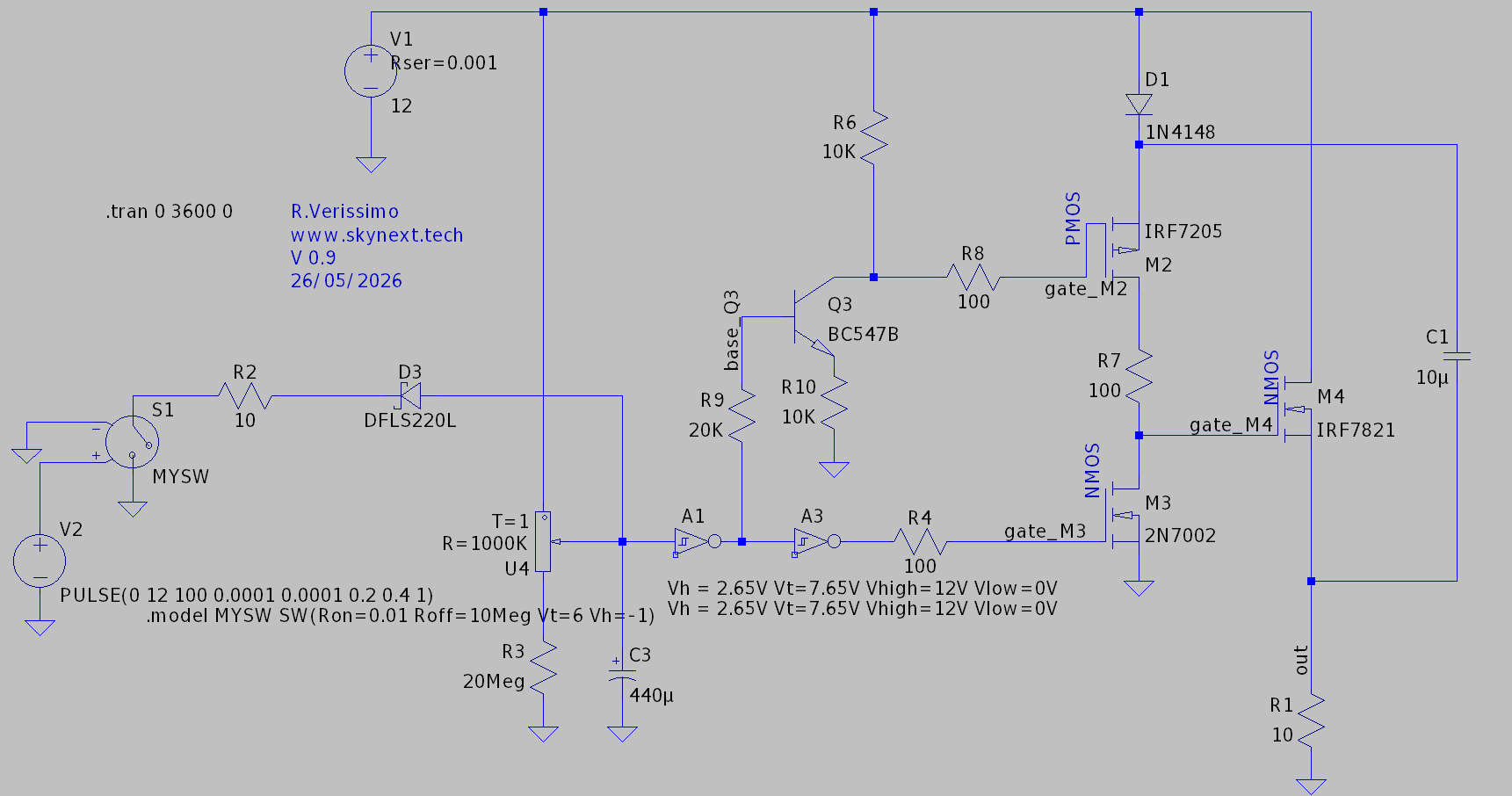
Here we present a fully solid state timer delay off high side NMOS switch, thus with low Rds ON. The power to the load is turned on through a pulse (such as one supplied by a spring loaded pushbutton), latches, and turns off based on the timing constant of a RC network.
Giving the maximum rating of the CD40106 Schmitt trigger used here, the maximum switched voltage is around 18V. A higher voltage rated Schmitt trigger inverter would allow 24V operation, and using MOSFET rated above Vds of 30V would push operation voltages into 48V or more.
The transient connection of the switch S1 discharges the capacitor C3 through D3 to ground, bringing temporarily the schmitt trigger input to ground potential. output of the trigger goes to logic 0V, while the inverting input goes to logic high. A CD40106 schmitt trigger can be used to implement complementary outputs, by daisy chaining two stages as shown in the schematic (A1 and A3). The operational parameters of the CD40106 at 12V have been calculated from the datasheet and added to the model.
In the low voltage state, the first inverting output of the schmitt trigger A1 is in logic high, sinking current into Q3 base, which has the effect to lower gate potential of PMOS M2, turning it on, and supplying bootstrap capacitor voltage to M4, which turns it on and performs the intended high side switching function, While schmitt trigger A3 output voltage goes 0V, turning M3 firmly off and preventing fast discharge of C1.
When the RC network charges back above Vhigh threshold, M2 is turned off, which has the effect of stopping the supply of voltage from the bootstrap capacitor to M4, and bringing the gate of M4 to ground through the turn on of M3. This effectively turns off M4.
Giving the low gate charge and leak of modern NMOS, the bootstrap capacitor C1 can supply voltage to the gate of M4 over a time far longer than the time constant of the RC network made with U4 + R3 and C3.
Note that M2 does not handle large currents in that circuit. A smaller footprint PMOS could be used, rated for logic Vgs levels (such as -5V)
Note that the transition Vhigh and Vlow voltage of the CD40106 used are linear functions of supply voltage, Which means that a higher or lower Vcc operation as supplied from a battery should not change the minimum and maximum delays achieveable significantly.
Resistor R7 acts as a current limiting resistor for gate current but also during switching of M2 and M3, which could temporarily provide a low impedance path to ground. Note that CD40106 propagation delay using two stages in a daisy chain have the effect of introducing a small dead time between M2 and M3 switching, thus mitigating that unwanted effect.
We can offer assistance and task offloading in audio projects, power electronics and metrology projects, MCU firmware development assistance and consulting. Feel free to contact us by mail at
and provide us a general description of your project and how you think we can help, so we can discuss further.
Our current areas of expertise :
Ltspice modelling for analog and mixed signals, and general drafting of circuits.
NXP iMXRT1060 based MCUs firmwares and rapid prototyping as well as EDA sketching
Assistance in coding for Steinberg VST3 plugins.
USB host and device modes for aforementioned MCU
DAC / ADC interfacing.
Proof-reading and review of LLM generated documentation.
Prompt engineering for general purpose electronic projects.
Standard rates :
From 40 EUR/hour depending on area of expertise, project complexity, and timing constraints.
TL072 Op-Amp model or any other Audio grade suitable op-amp
Explanation :
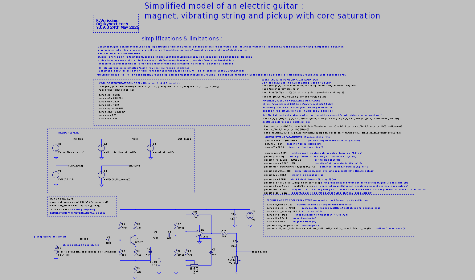
It assumes a single pickup with a copper wire wound around a Nickel Steel alloy core. Saturation is modeled.
In a realistic model, the magnetic excitation of the coil is as follows :
A) Magnet generates (magnetostatic equation) magnetic field. (2)
B) Vibrating string is magnetized. Creates a time varying magnetic field according to motion equations (1) & (4)
C) Time varying magnetic field is picked up by the coil wrapped around the pickup pole cores.
Because of the limitations of integration in Ltspice (time integral support, but not space integrals), the model of B) has been simplified – As if the magnet was vibrating like a string at a distance of the pickup, but taking into account geometry. A better model would be possible using “C++ black boxes” as it is possible now with QSpice, as the DLL engine is Turing complete which allows to render space integrals easily. The model of B) excited by A) is doable in QSpice and is explained in the paper (4). So B) has been simplified to a simple coupling parameter int the form of a factor “chi_wire” (or wire magnetic susceptibility).
Note that the code for such a model of B) has been explored as such, but not validated. It may be added here in a future release.
Finally the core Mechanical model is simplified and according to (1) :
It assumes a string displacement along the Z axis only, and bridge reaction is not modeled.
Bias magnetic field is modelled and as a notable contribution if the pickup core saturation is modelled.
Note that the coil is assumed to be wrapped around a single pole (as just one string is modeled), number of turns has been decreased to take into account the tighter magnetic coupling.
Pickup flux is the sum of self inductance times current + induced flux from time varying magnetic field. Since the preamp is very high impedance the current is negligible and only the EMF from the magnetic field has sensible contribution.
Finally a preamp has been added. (5)
References :
(1) Solving the Sound of a Guitar String Jason Pelc December 10, 2007 (Submitted as coursework for Physics 210, Stanford University, Fall 2007)
(4) Exact expression for the magnetic field of a finite cylinder with arbitrary uniform magnetization Alessio Caciagli 1, Roel J. Baars 1, Albert P. Philipse, Bonny W.M. Kuipers ⇑
A substantial advantage of the Arduino Due MCU is the native USB High Speed interface allowing up to 480 Mbps transfers. Another option are the costlier Teensy boards that are really mature and provide a solid framework for USB bulk endpoints data interfaces not limited to ttyACM Serial over USB interfaces. However, it is absolutely possible to integrate a vendor (custom) bulk pair of endpoints (IN and OUT) on Arduino Due, it’s just that there is not much documentation besides examples such as the MIDI USB library and articles about it.
In this article, we leveraged the power of LLMs advices and validated them through testing to add support for an additional pair of endpoints, such that the native SerialUSB object could still be used (for telemetry, communication control or debugging)
Incentive.
Using a custom pair of endpoints has several advantages over SerialUSB.
They can be tweaked on the MCU so as to be adapted to the maximum required transfer rate, such as number of BANKs used (up to 3) and NBTRANS.
On the host side, since the endpoints are not claimed by the OS Serial over USB driver, transfers are more straightforward and do not suffer from the long chain of complex buffers used by the driver and the ttyACM stack. Interfacing can be done in user space using libusb.
No tty re-configuring issues, (such as special character handling, line discipline, throttling, etc) Note that tty were historically made for terminals and text, not binary data transfers)
On the downside, detection of host ready or not conditions can be different or tricker than ttyACM, as the linestate logic (DTR emulation) is not present on a custom bulk interface. The idea is thus to keep the Serial USB link for telemetry, control, and debugging, and initiate data transfer once the proper Serial USB transmission. Note that on linux detecting a DTR down condition on SerialUSB does not seem to work as well as on MS Windows from a MCU use case perspective, This all situation needs unfortunately to resort to watchdogs to re-establish a broken connection when the host is electrically connected. but not listening.
Also ttyACM or the tty stack seem to behave on linux so as to limit to 64 bytes max the data fetched fro; each read() call on the port. Since USB 2.0 max packet size is 512 byte, libusb allows more efficient call economy, although the mechanism is largely different, since IO read calls are not used, but library specific “transfer submits”.
In our case, the packet size is 96 byte. All writes to USB from the MCU sides will be 96 byte. Note that packet sizes and URB sizes, ZLP (zero length packets) and libusb “transfer” sizes concepts are important as understanding and managing them properly can save you a lot of headaches.
libusb also has a quite steep learning curve. However, through LLM assistance, we successfully made such an interface.
Note that for “real time” transfers or transfers with timing constraints (continuous flow) a separate FIFO (sched_fifo) thread is preferable on the host side. This will be shown in that example.
The MCU code.
Optimized for 1 to 4 MB/s transfers.
The latest Arduino Due (SAM) framework available in Arduino IDE and Platform IO provide helper objects (Pluggable USB), defines / macros to help in creating additional endpoints.
First we will need some defines that will setup USB endpoint types configuration bitmasks. Here comes the first versatile configuration as these elements are not exposed for the SerialUSB interface.
Note that we use max packet size of 512 byte, which is the maximum allowed by the USB 2.0 High speed standard. EPBK_n_BANK and NBTRANS_p_TRANS admit n and p values up to 3, at the expense of more MCU SRAM used, depending on the throughput required they can be increased and profiled for best performance.
It should be known that EPBK_n_BANK consumes a limited amount of memory available (max 4KB), In the above case, n = 1 consumes 512 bytes. Reaching the hard limit is easy, as the total number of endpoints provided by all interfaces has to be taken into account.
Note that the IN and OUT endpoints are from the reference point of the host (the computer in that case) so a IN endpoint is used to send data from the MCU to the computer.
Then we need to do some class inheritance magic to extend the PluggableUSB module base class and implement our custom calls that will be used for enumeration and communication setup as well as data transfers.
Once our class properly inherits the Pluggable USB module base class, we can create the object
DataBulk_ USBData;
And use it to send data to the computer :
USBData.write((void*) Data2,sizeof(Data2)); // uses our bulk endpoint, processed on the host by// libusb 1.0// sizeof(Data2) is 96 bytes.SerialUSB.println("USB data sent") // uses the native USB port Serial over USB, processed on the host by the ttyACM driver
Testing enumeration on the host
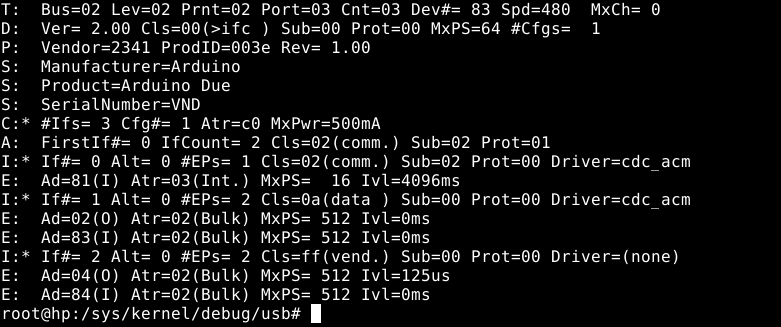
To check for proper enumeration once the above code has been added to your sketch, compiled, and uploaded to the MCU is straightforward.
As root, run :
cat/sys/kernel/debug/usb/devices
And the bottom relevant lines (ep 04 and 84 of interface 2) should appear once the native USB port is plugged to the computer :
Libusb code
Now it is time to add libusb code to your C++ project, and add some #define and declarations
// BULK USB VENDOR MODE#include<libusb.h>//defines for bulk interface#defineURB_SIZE 96 // In our case URB_SIZE = Packet size = 96 bytes#defineN_URBS 32 // 16 to 32 URBS in flight seems ok for data rates in the low MB/s range#defineVID 0x2341 // vendor ID of our device#definePID 0x003e // product ID of our device#defineUSB_BULK_IFACE 0x2 // Bulk interface ID#defineEP_IN 0x84 // endpoint IN address#defineEP_OUT 0x4 // endpoint OUT address (not used)struct libusb_transfer *usbxfer[N_URBS];uint8_t*usbbuf[N_URBS];std::atomic_bool readbulk_exit(false);std::atomic_bool USB_transfer_active(true);libusb_context *ctx;libusb_device_handle *h;
Add a FIFO scheduled thread (bulk_read_thread) that will make the initial transfer submit as well as pump the event driven libusb.
the sched_priority attribute is very important. use the ps command to get SCHED_FIFO threads and their priorities, and set priority accordingly as to obtain a stable data flow and so as not make the system irresponsive or lag. Remember that SCHED_FIFO threads have precedence over most of other threads on a system (SCHED_OTHER)
The Thread function follows :
void*BulkReadThread(void*arg){mlockall(MCL_CURRENT | MCL_FUTURE);DebugPrint(dbgstr("Enter USB Bulk read thread"),0);if(USE_BULK){for(int i =0; i < N_URBS; i++){libusb_submit_transfer(usbxfer[i]);}}while(!(readbulk_exit.load())){ //usleep(100);libusb_handle_events(ctx); //DebugPrint(dbgstr("PutSerialSamples ok"),0); sched_yield();}sched_yield();return0;}
The readbulk_exit atomic boolean is used to signal the thread (externally) that it needs to stop USB event polling operations which will quench transfers, Which is used in a graceful program termination.
This thread does not populate directly the data buffer so it can be consumed. It only submits initial transfer requests and pumps events through libusb_handle_events(ctx) The setup of the population of the buffer is done by libusb_fill_bulk_transfer() once, where we supply a callback function, rx_usb_bulk(). See below.
sched_yield() in that case is quite important as it guarantees some throttling and helps with system responsiveness. It relinquishes the CPU and other sched_fifo threads can be immediately processed, regardless of priority.
mlockall() is an optimization as it locks all pages in memory and prevents paging. It may have profound effects on allocation, and should probably happen when most of allocation is done or memory reserved using techniques appropriate, which are beyond the scope of this article. Use with caution.
Of course, now we also need to initialize the whole libusb stack to handle our device :
libusb_init(&ctx);libusb_set_option(ctx,LIBUSB_OPTION_LOG_LEVEL,LIBUSB_LOG_LEVEL_WARNING);h =libusb_open_device_with_vid_pid(ctx,VID,PID);if(!h){DebugPrint(dbgstr("USB open device failed, is it plugged ?"),0);fflush(stdout);return1;}DebugPrint(dbgstr("USB open device OK"),0);if(libusb_kernel_driver_active(h,USB_BULK_IFACE)==1){libusb_detach_kernel_driver(h,USB_BULK_IFACE);DebugPrint(dbgstr("kernel driver detach OK (should not happen, no driver should be attached)."),0);}if(libusb_claim_interface(h,USB_BULK_IFACE)<0){DebugPrint(dbgstr("USB claim interface failed."),0);fflush(stdout);return1;}DebugPrint(dbgstr("USB claim interface OK."),0);for(uint8_t i =0; i < N_URBS; i++){usbbuf[i]=(uint8_t*)aligned_alloc(64,URB_SIZE);usbxfer[i]=libusb_alloc_transfer(0);libusb_fill_bulk_transfer(usbxfer[i], h, EP_IN,usbbuf[i], URB_SIZE, rx_usb_bulk,NULL,0);}readbulk_exit.store(true);
And finally, the rx_usb_bulk() callback function :
staticvoidrx_usb_bulk(struct libusb_transfer *t){if(t->status== LIBUSB_TRANSFER_COMPLETED){if(t->actual_length>0){PutSamplesUSB(t->buffer,t->actual_length); //DebugPrint(dbgstr("Processing of USB transfer buffer,t->actual_length"),t->actual_length,0);}if(USB_transfer_active.load()){libusb_submit_transfer(t); //reschedule transfer immediately, unless signalled to stop.}}}
PutSamplesUSB() is a user project function that handles incoming buffer data, to populate, let’s say a circular buffer from the t->buffer source.
USB_transfer_active is an atomic boolean variable that signals to stop submitting new transfers. It needs to be set to false first before setting readbulk_exit to true (that in turns make the the thread that processes libusb events to join). This happens usually in the graceful process exit / cleanup routines. See below.
Cleanup
Cleanup is required in traditional C++ fashion as well as libusb required calls. But first the dedicated thread that does the libusb event polling must be notified to join.
USB_transfer_active.store(false);DebugPrint(dbgstr("setting USB_transfer_active to false (won't submit new transfers)"),0);for(int i=0; i < N_URBS;i++){libusb_cancel_transfer(usbxfer[i]);DebugPrint(dbgstr("cancelling pending transfers, index="),i,0);}usleep(10000);libusb_release_interface(h,USB_BULK_IFACE);DebugPrint(dbgstr("interface released"),0);libusb_close(h);DebugPrint(dbgstr("USB device handle closed"),0);readbulk_exit.store(true);int s =pthread_join(bulk_read_thread,nullptr); // waiting for USB bulk read thread to joinif(s ==0){DebugPrint(dbgstr("USB bulk read thread joined"),s,0);libusb_exit(ctx);DebugPrint(dbgstr("libusb exit"),0);}
Here we use the boolean state variables to communicate with the thread to halt USB communication before releasing libusb resources.
This concludes the article about adding USB 2.0 (High-Speed) bulk endpoints on Arduino Due MCU and libusb interfacing on Linux.
This is a quick update on our flagship product development, PMU-001. Since October 2024, we put great effort in developing it. The PMU-001 USB device is intended for electricians that need a portable and reasonably affordable field device which provides the following features :
Robust GNSS based synchrophasor measurement, IEEE Std C37.118-2005 compliant with network bindings.
6 channel analysis (3 voltage channels, 3 current channels, 2 auxiliary channels)
4 quadrant power analysis
Positive, negative and zero sequence vector decomposition
logging and real-time (within standard delay requirement) equispaced sampling of frequency deviation from nominal mains
Harmonics analysis and THD display and logging
waveform logging
USB 2.0 high speed device, hardware sampling rate 48 ksps.
Lightweight NCURSES interface allowing use across low speed / character based tty
Integrated class 0.1 voltage measurement transformers with secondary DAC TVS protection / clamping on top of internal DAC protection.
1000V AC transformer winding voltage tolerance.
Line to Line or Line to Neutral voltage measurements (120V up to 240V AC / 208V AC to 400V AC nominal voltage +15% tolerance)
It leverages the power of a personal computer for high level analysis, reducing hardware costs, the software payload is C++ based and works on Linux distributions. Microsoft Windows porting is planned in the future.
A fully functional hardware and software prototype is planned for Q3 2026.
Most of the work is now dedicated on GPS disciplining and TCXO clocking, as well as cross channel analysis for four quadrant measurement, and delay vs filtering efficiency real time tuning. IEEE Std C37.118-2005 compliance will require rigorous conformity testing and calibration. At that time, a crowdfunding effort with pre-order priority will be put into effect, allowing trade electricians to have priority access to the device in the beta phase.
Here are some video and screen capture teasers :
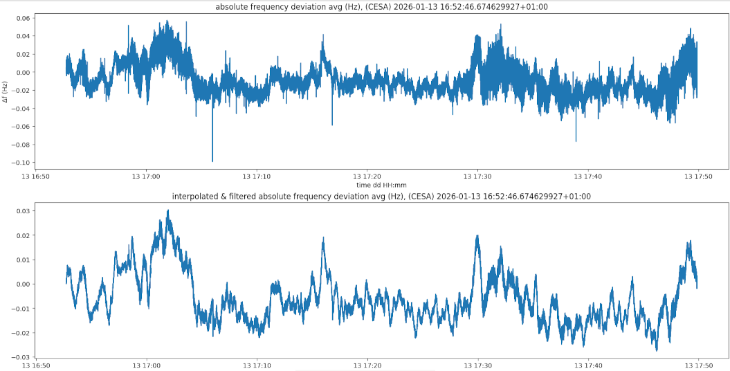
NCURSES display of frequency deviation, ROCOF, harmonic analysis, amplitude analysis, and synchrophasor data. Single phase to neutral display.top chart : raw frequency deviation measurements at 100 Hz sampling rate; bottom chart LP filtered at 10 Hz cutoff frequency and PCHIP interpolated/equispaced frequency deviation measurements. Network PMU connection to PMU-001 using GPA PMU Connection Tester tool, displaying a single voltage channel synchrophasor and frequency measurements.Websocket synchrophasor and frequency deviation interface (alpha version)
We wish everyone a fruitful 2026 year. Stay tuned for updates !