The knee-breaker
Analog compressor designed from scratch
| NOTE: the download link is at the end of this article. |
NOTE : A VST3 plugin was made implementing the knee management part of this compressor, more info here :
https://www.skynext.tech/index.php/2023/05/31/thermionic-vst3
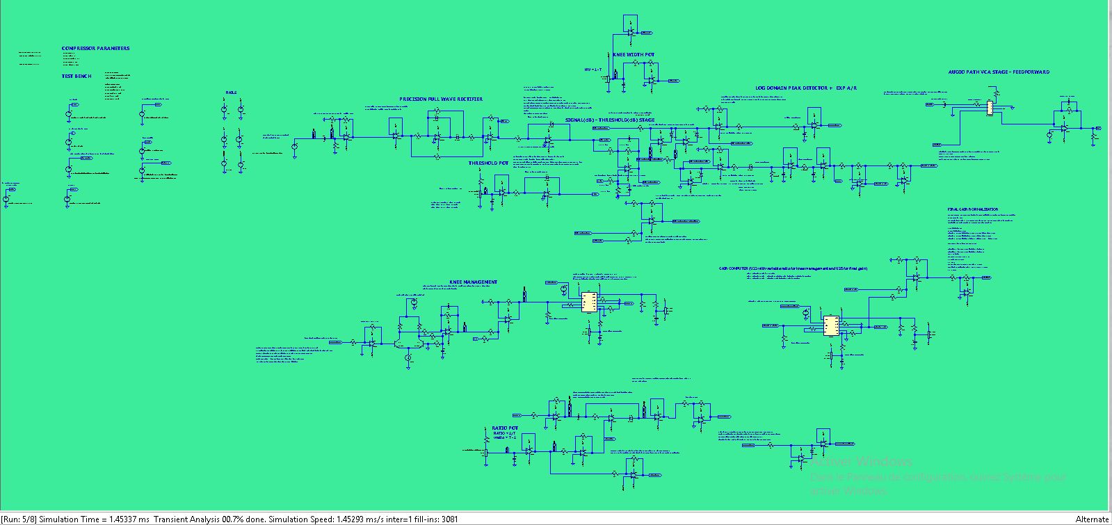
This post demonstrates a VCA-based compressor with a variable knee.
The methodology used to design this compressor was to draw no inspiration from existing VCA compressor design and rather start from compressor theory alone.
The fact that I had no previous exposure to VCA designs and started with no previous experience in analog compressor design is a double-edged sword.
On the one hand, it could end up with novel and unexplored means of achieving certain effects and sound coloration,
On the other hand, it could lead to questionable choices or overly complicated designs.
There is also a big risk of getting a design that works well “in silicon”, that is, running well in a SPICE simulator, but would offer subpar performance in any realistic
implementation. I am mainly thinking about SNR characteristics.
An understanding of theory is indeed required to build a compressor that achieves its intended goal, dynamic range compression.
The following paper is a good starting point :
[1] “Digital Dynamic Range Compressor Design— A Tutorial and Analysis” from Giannoulis, Massberg, and Reiss.
Our design however diverges quite fast from the standard gain computer architectures provided in the paper.
Figure 7 of [1] introduces the basic configurations of gain computers and sidechain detectors.
Our design is a variant of the log domain detector, (7.c), in which the level detector comes before the gain computer.
Since our level detector and A/R stages work on a log signal, and our A/R stages, being RC single pole filters exhibit exp. behavior in transient response,
which means that the overall A/R envelope with respect to the linear domain is also linear (log and exp cancel out to give a linear envelope).
This is one thing.
The next divergence from a classic compressor is the knee implementation.
Here we embarked in a really experimental direction.
Usually, the knee is an amplitude band of the signal, in which the gain computer does not apply the full ratio. This bandwidth is called the kneewidth, centered around the threshold.
At threshold – knee, the compressor applies a unity ratio, which means no compression.
at threshold + knee, the compressor applies full ratio, that is the set compression.
The goal of the knee is to provide a smooth transition between these two extremes.
When using high ratios which get close to limiting range, that is particularly useful.
Figure (4) of [1] shows the piecewise definition of the gain computer.
- Yg is the output sample
- Xg is the input sample
- T is the threshold
- W is the kneewidth
$$ 2(X_{g} -T) < \frac{W}{2} \Rightarrow X_{g} $$
$$ \left |2(X_{g} -T) \right | \leqslant W \Rightarrow X_{g} + \frac{(\frac{1}{R} – 1)(X_{g} -T +\frac{W}{2})^{2}}{2W} $$
$$ 2(X_{g} -T) > W \Rightarrow T + \frac{X_{g} -T}{R} $$
(1) (2) and (3) form the piecewise definition of gain computer function.
This function in the knee zone uses a quadratic function to make the junction smooth.
Making a smooth junction between two secant lines is a Bézier curve.
Our approach is experimental in the sense that it uses :
the sidechain signal bounded between -W/2 and W/2 as the ratio modulator, further, it applies an attack/release to that bounded signal.
To achieve proper results that A/R settings should not diverge much from the main peak detector A/R, or the time constants will lose correlation and the knee may be applied outside of the knee range or not at all. (ganged potentiometers would be required).
Furthermore, the processed knee control signal after the A/R range is passed through a tanh() function cell using a BJT differential pair.
The resulting control signal does not guarantee smooth branching between the two gain lines and may induce undershoot/overshoot.
We expect it to introduce distortion in some cases and make the knee setting a complex task, however, it is interesting from an FX compressor point of view.
Most of the circuit complexity is found in the processing of the tanh cell signal to normalize it so the compressor acts as a compressor and does not expand the signal,
and also provides no more than compression at ratio levels at the upper exit of the knee width zone.
Description of the knee control signal path.
As said before, we clip the log detector signal centered around the threshold between -w/2 and w/2.
Then we apply a similar A/R envelope. Then we use U22 opamp to control the gain of the input signal to the tanh() cell. A stronger signal will result in a tanh output being more “square”
The output of the tanh() cell is then passed to a normalizer using a VCA824 (U41) that ensures the signal “tanh_norm” is constrained : “vratio_buf” < “tanh_norm” < 0V )
This assumes that the previous tanh() cell signal is well behaved : -0.5V < “tanh_out” < 0.5V
if not, the following clamping stage will take care of unwanted excursions.
For normalization, we use a VCA824 IC to perform that function. This VCA is a linear domain VCA. It is designed for HF but should work well at audio frequencies.
However, it would incur some additional costs in the final product. There is also the issue of input/output voltage offsets that require calibration.
Then we have a clamping stage for supplementary protection :
This clamps “tanh_out_gain_inv” output positive excursions to the “- vratio” level (positive value).
positive excursions should not happen unless the tanh() cell current sink is above 247µA and the signal entering the tanh() cell makes the cell saturate.
If that were to happen, “tanh_out_gain_inv” would go above “-vratio”.
Finally, We added a bit of extra precaution so that gain voltage “tanh_out_clamp2_clip_buf” fed to the U23 VCA824 never goes above 0V.
tanh() normalization and clamping action is not perfect, as well as U41 VCA824 always has some offset despite calibration, so we clip above 0V here.
The result is our modulated ratio gain signal. We use another VCA824 (U23) to apply this ratio to gain_before_ratio_inv as a part of the gain computer architecture.
The rest of the gain computer is a standard implementation.
Before the gain control signal is sent to the THAT2180 IC, it needs to be normalized so as to apply a 20(log10(x)) transfer function.
This allows a simpler calibration when doing measurements.
A gain correction factor is done by U37, taking into account the gain factor of the THAT2180 and the transfer function of the diode linear to log signal converter that is situated at the start of the sidechain, after the full wave rectifier.
We use a high current, low output impedance op-amp for U37, as the THAT2180 requires a low impedance gain control signal.
Note that the threshold stage setting also uses a linear-to-log converter instead of a log potentiometer. The idea was to thermally couple the matched diodes D4 and D8 so that when there are temperature fluctuations, the threshold does not change much.
Use of the model :
Set the parameters.
“threshold” at 1 is -oo dB while 0 is 0dB
“kneewidth” close to 1 is 0dB while 0 is +inf dB
“ratio” is the compressor ratio.
“attack” and “release” are resistance values of the attack/release stages.
Higher attack resistance value -> faster attack (attack capacitor charges quicker)
Higher release resistance value -> slower release (release capacitor discharges slower)
Choose the input source signal
Edit the B1 voltage source and specify the voltage source to use. the “1V” voltage source uses a low frequency (20 Hz signal) that allows seeing the action of the attack and release settings. there are also pulse/square waveforms, a triangle, and one using a wave file as input, do not forget to set the input and output waveform filenames to your requirements.
Load the waveform settings.
There are three waveform settings :
- compressor_v0.9_monitor.plt: to compare input signal with compressor output.
- compressor_v0.9_tanh.plt: to inspect the knee computer.
- compressor_v0.9_gain_computer.plt: to inspect the gain computer.
Caveats / possible improvements :
- The input AC coupling to both the sidechain and THAT2180 is sketchy. it could generate phase problems.
- There is no makeup gain in this circuit.
- There is no balanced input to unbalanced converters, nor unbalanced to balanced output.
However, adding these would slow even more the simulation which is already really slow on a dual Xeon E5-2430v2 ( between 50 and 100µs/s) When using a wave file.
Expect 2.75 hours for 1 sec of simulation at this rate.
However, using standard test bench inputs gets a much higher simulation rate. (in the 2 to 3 ms/s range)
- The knee control signal (between U33 and U46 stages) is a bipolar signal, which means we have to discard the diode between this stage, to allow the signal negative excursions, This stage is no more a decoupled attack/release stage but simply a first-order LP filter. The time constant however is determined by the {release} parameter. and is the same as the A/R signal stage in our model.
- The two parallel paths with different A/R parameters (one subjected to a full-fledged A/R while the other to a simple LP filter, plus the different amplitudes due to the knee width selection give overall a different signal profile at the attack vs at the release, even when using same resistor values for attack and release resistors. this gives rise while using certain knee settings to a different effective threshold at attack vs release. The symmetrical wave shape subject to this won’t be symmetrical anymore.
- Wide knee widths give wide knee width signal amplitudes between the two clip values (-w/2 and w/2). In the case of small widths, the resulting signal fed to the tanh_out stage may not be sufficient to drive it to saturation. A better implementation would normalize this signal based on kneewidth. For now, one has to boost U22 gain for small widths to ensure saturation. Failure to do so would make the ratio stage fail to reach its target ratio.
- Control of tanh() saturation by means of U22/R65 has a large influence on the application speed of the final ratio, which means its effect may “take over” the attack release characteristics of the classical A/R settings.
As a conclusion, using a tanh() cell was a questionable design choice if ease of use is a prime concern, but introduces interesting waveshaping effects (if applied to an instrument, with very fast attacks and releases)
it also allows knees ‘harder’ than no “knee”. The effect can be sought as a transition from a unity ratio to a ratio more than intended before a gradual recovery to the desired ratio. The precise reason for this behavior would require an in-depth analysis of the simulation and also a practical simulation to see if that can be reproduced. It could be useful to limit fast transients since at the crossing of the threshold a super hard knee would help to bring them in check before reverting to the desired ratio
I am posting the asc without the additional required components for copyright reasons.
Simulation Data
We will now show the compressor behavior before a full calibration is done on the output gain stage op-amp final amplifier, using theoretical values.
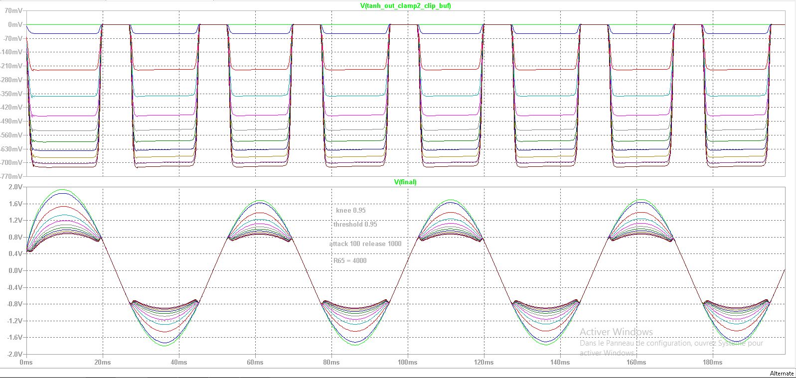
Figure 1 : This first plot shows a step of the parameter knee width with constant tanh() gain. for smaller widths, the tanh() cell fails to saturate and the full ratio is not applied. resulting in less compression. For larger widths, compression starts earlier in our design because the main gain computer applies the A/R envelope at (threshold – kneewidth/2), to this the distortion effects induced by the tanh() cell are compounded. overall it achieves more compression at larger widths. which is quite paradoxical.
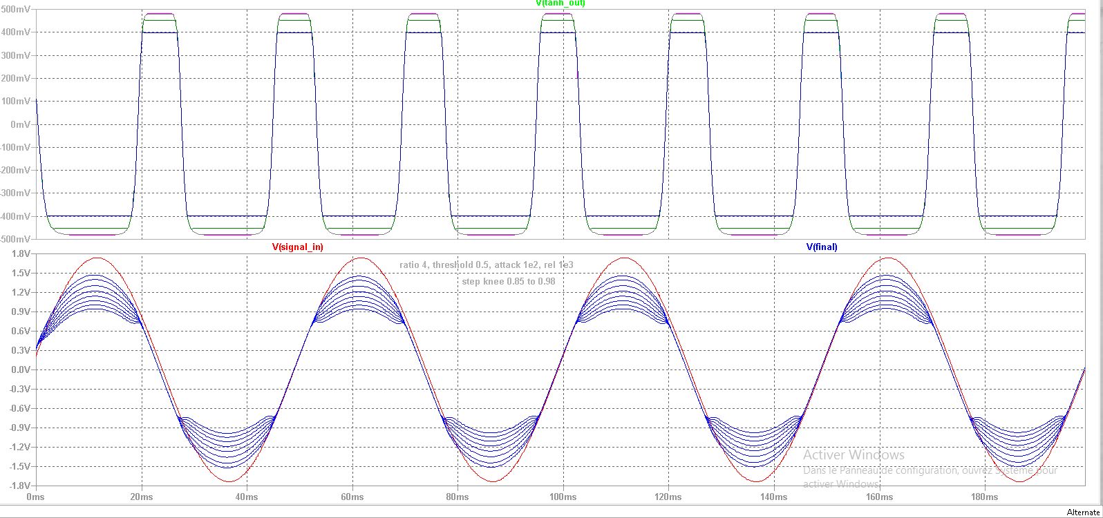
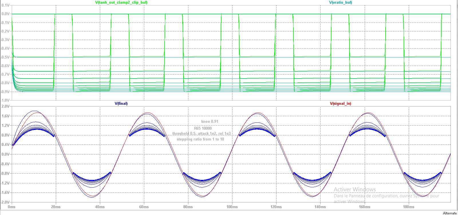
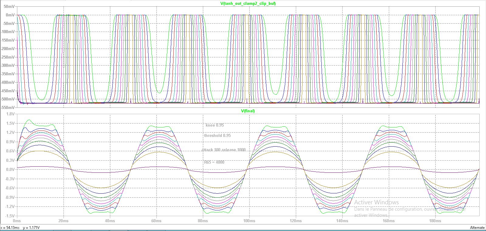
Figure 2 : The second plot uses the same parameter stepping with a higher input gain to the tanh() cell, setting resistor R65 to 10k. The overall gain response is more or less the same for small knee widths, while larger knee widths exhibit a dramatic distortion effect.
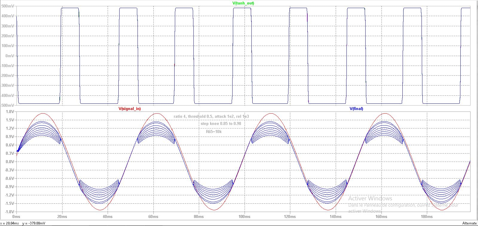
Figure 3, We stepped the tanh() cell input gain resistor. the knee inversion from soft to “hardcore” is clearly visible
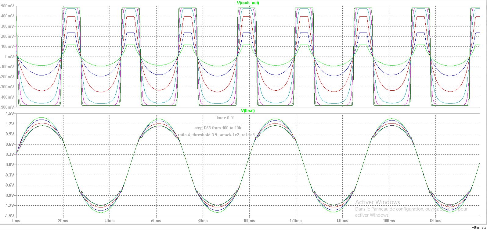
Figure 4 : Zooming in on the previous figure to show knee inversion clearly :
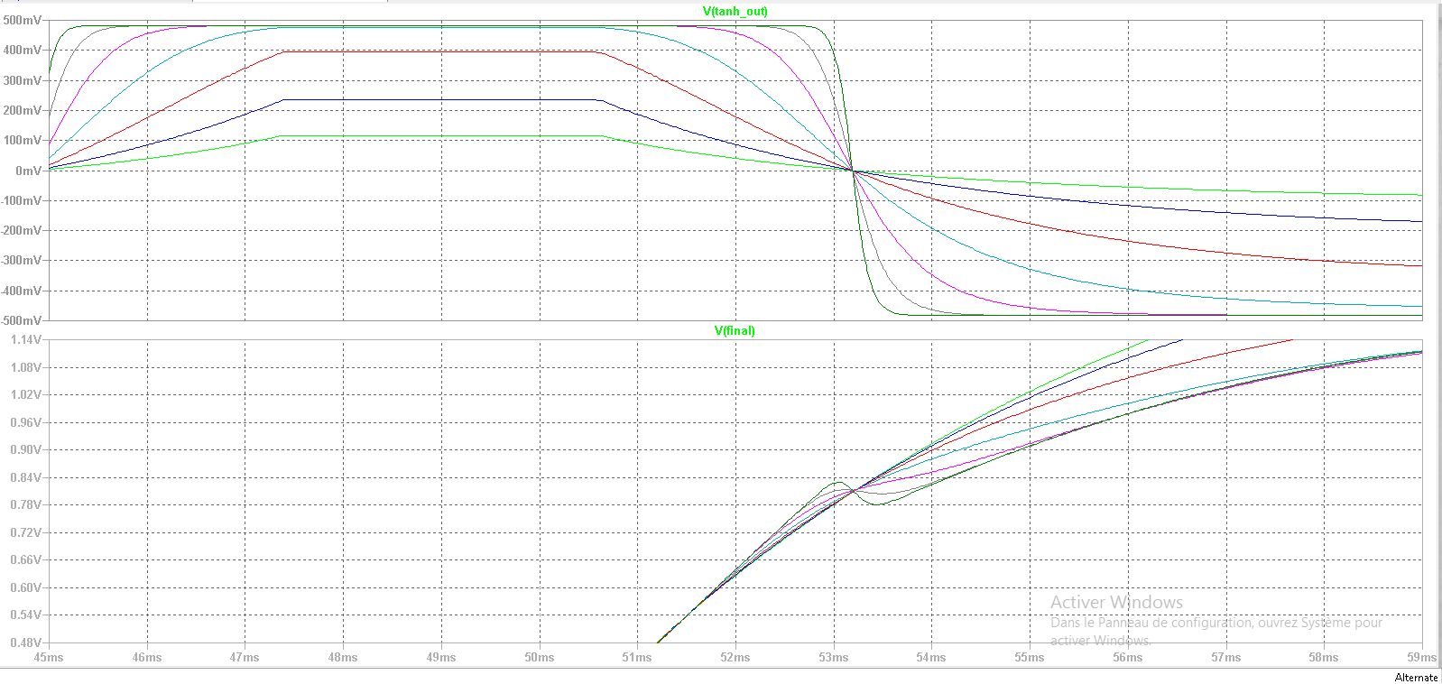
Figure 5 : We step the ratio from 1 to 10 by increments of 1 to show a more classic compressor behavior. The R65 resistor is set at 500 so the tanh() cell is not saturated. Gain reduction seems to hit a hard limit before reaching to effective ratio of 10. The compressor shows and effective ratio of 1.56 where it should be 2, 2.10 where it should be 6, and 2.23 where it should be 10. The gain computer works on a logarithmic signal, but the THAT2180 IC is an exponential control IC, that is, it expects dB input, so the result should be linear. We will have to investigate this. Part of the problem is due to the tanh() cell not being saturated but that does not explain such low effective ratios.
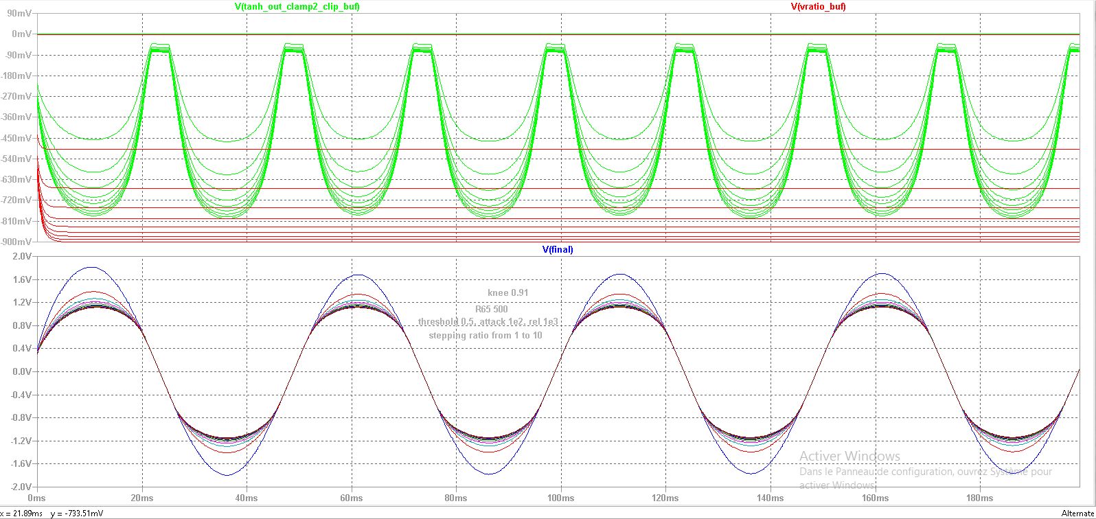
Figure 6 : Same problem. We will have to check the R26 value that sets the U37 gain used in the final gain normalization stage. Also maybe a diode voltage drop was not accounted for. in the A/R stage. The best would be to set an acceptable knee width (not too small to prevent inversions) and not too big to lower the ratio, Set a high ratio, and perform calibration by selecting a better value for R26 and then re-check compression for a ratio of 2. Fortunately, unit ratio results in a more or less identical signal which means that there is probably not any unaccounted offset in the gain/knee computers.
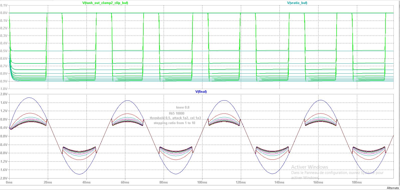
Now in Figure 8, we see an adequate ratio using a knee of 0.8 but at the expense of a very hard knee and signal distortion, because of that, the signal appears to have high compression because of that offset. In reality, it is more like a higher compression obtained through lowering the threshold (which the knee setting does)
In the end, the sensible solution was to recalibrate the final gain normalization op-amp, at the maximum rated compression level, let’s a ratio of 20, so that the (linear) ratio of the output of the non-processed signal above the threshold to the output of the processed signal above the threshold is roughly equal to 20, This is done while setting other parameters to midrange values the threshold to -6dB. This was done with the knee-width computer disconnected, and R55 connected to ground instead. In the end, we set the R26 resistor value to 35k instead of 20.8k for theory.
Next, We set the ratio back to 1 and reconnect the knee width computer since he is responsible for applying the ratio. We check that both amplitudes of the input and output signal match. The small discrepancies are probably from the VCA824’s small remaining offsets.
The process would then need to compute the ratios at step intervals and mark the potentiometer accordingly.
Figure 9: It’s much better now ! The potentiometer pot also has been replaced by an exponential pot to allow finer resolution for low profiles.
This is the model for the exponential pot that I used :
.SUBCKT exppot 1 2 3 T=0.5
.param tap={limit(T,1m,.999)}
.param stiff={limit(stiff,1,10000)}

R0 1 3 {R*exp(-tap*ln(R*stiff))}
R1 3 2 {R*(1-exp(-tap*ln(R*stiff)))}
.ENDS
Figure 10 : For the sake of completeness, we will now step the threshold, setting the effective ratio near 4.
Model Download
You need these models in your library to make the simulation run properly :
- TL072
- LT6244 (should be included in Ltspice, check for updates if not)
- LT1217 (should be included in Ltspice, check for updates if not)
- THAT2180
- VCA824
Leave a Reply