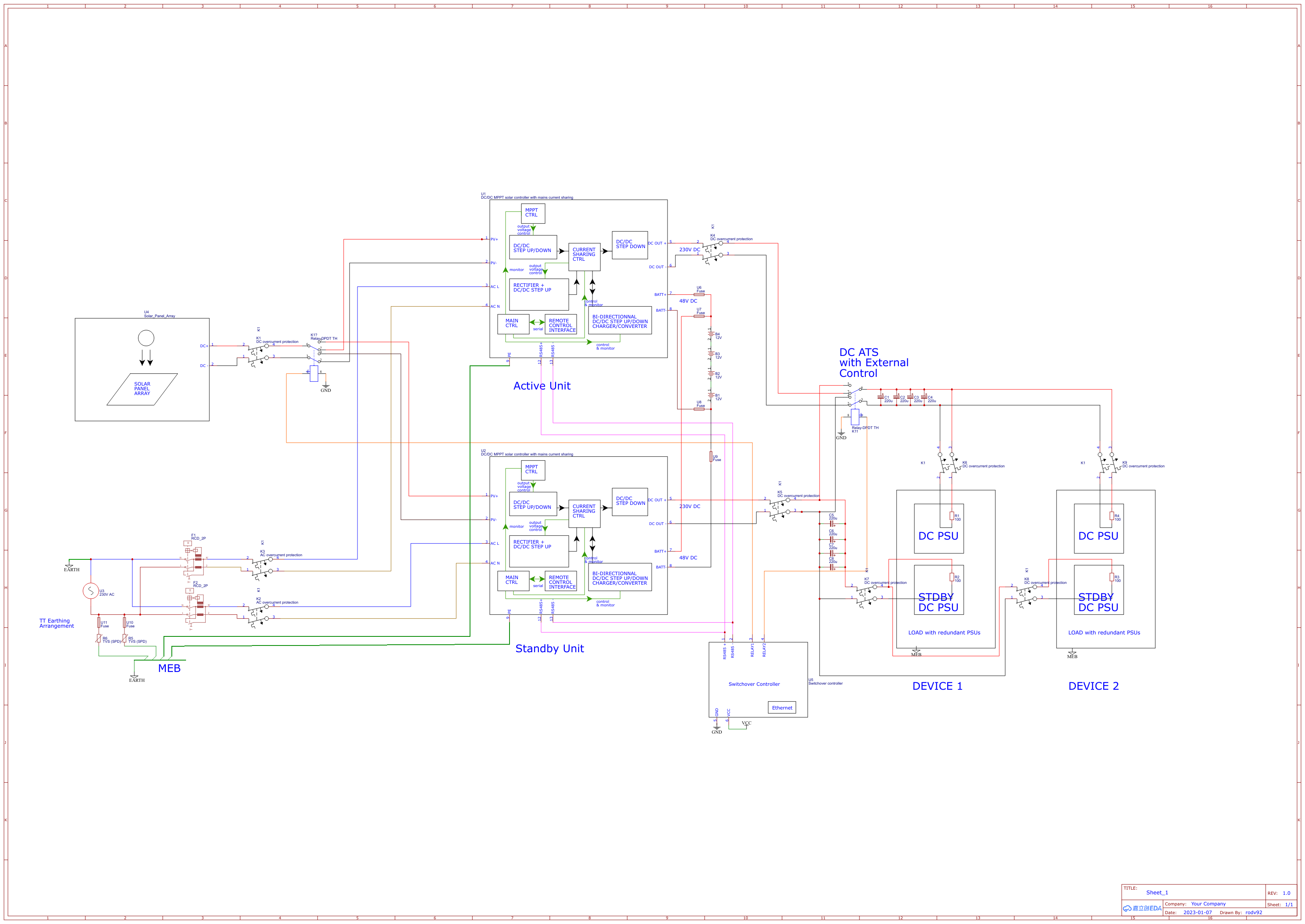
230V DC redundant network with a renewable energy source and AC auxiliary power input.
The goal of this design is to get rid of :
- The inverter stage of UPS or Grid tie inverter technology
- The rectifier and PFC stage of PSUs
And make use of a renewable power source such as solar panel array
The core of the design is a DC/DC converter with MPPT, current sharing, battery management, It uses an auxiliary AC power input to allow for operation when solar panels do not provide enough power.
Such designs already exist, but they usually contain an inverter stage to output pure sine mains voltage AC.
The hard part of these designs, whether they contain an inverter stage or not at the output is the current sharing stage.
Finely controlled current sharing requires voltage control of all the input sources. However, the output DC/DC step up/down converter stage that conditions solar panel output is dictated by the MPPT algorithm. The solution then is to perform control of the voltage output of the mains AC/DC step up converter stage.
However, by doing so, the load impedance seen by the solar DC converter changes, and upsets the MPPT algorithm that will try to compensate for that change by upseting the DC output voltage.
The current sharing algorithm is non-trivial.
A solution for fast prototyping could use a digital control algorithm to control the voltage of the mains AC/DC converter through a DAC.
A simulink model for such a device is a requirement before attempting any practical device.
It is better if the core UPS also provides battery equalizing/balancing through individual battery/cell links.
Equalizing links to the battery bank are not shown in the schematic.
The UPS has to revert the operation of the converter for battery current draw instead of charge in case of mains failure to supplement solar panel output.
Fortunately, bi-directionnal switch mode converters designs and IC exist for that design. They allow the usage of the same switching transformer for both charge and discharge.
In a 230V DC design, It is also beneficial to have battery banks operating at a voltage close to the operating voltage of other buses, to allow for a switching transformer ratio close to 1:1
The device schematic shows a standard telco 48V battery bank.
The same goes for the solar panel array, it also has the beneficial effect of reducing ohmic losses and requirements for larger cable sections.
Thus the solar DC/DC converter has to be able to accomodate with various solar panel arrays configurations. For this reason a step up/step down design is preferred.
Failure scenarios
To avoid a single point of failure, the core converter is assisted by a standby unit powering up the standby PSU of load devices.
The standby device is not connected to the solar panel array in standard operation and provides power from AC mains utility. It is connected to the battery bank but does not perform charging in nominal operation conditions.
In case of interruption of AC power to the standby unit, it powers itself and provides power to the standby PSU (that draw a very limited amount of power) through the battery bank.
In case of interruption of AC power to both units, the standby unit will perform the same way. The active unit will provide power from the solar panel array with assist from the battery bank.
Switchover operation.
Whenever the active unit encounters a fault, it is reported to the switchover controller, that chooses whether or not to transfer the load to the standby unit by remote controlling the ATS, and also performs transfer of the solar panel array source to the standby unit, if the fault requires it.
ATS should also be able to operate automatically without switchover input (it is an ATS after all) and switch to the standby or active unit in case of DC power loss from either unit.
It is recommended to use a DC/DC SSR based ATS for this operation to reduce switching time and required output capacitance that allow for long hold times of the voltage on the PSU power bus.
High voltage / High capacitance capacitors banks are expensive.
Electromechanical relays also have a limited rated number of cycles before failure compared to SSR. Note that the SSR ATS has to be rated for 230V DC, which can be harder to source than a DPDT relay for the same ratings.
A custom MOSFET based design can be implemented with either low side or high side switching or both. low side switching is prefered because of lower RDSon for NMOS devices, or the use of a voltage pump for high-side NMOS switching. This design implement both high side and low side switching to completely isolate the the active and standby core DC UPS.
Failure of the ATS to switch to the standby unit will be compensated by the standby DC PSU providing the load to the device, standby DC PSU bypass the ATS in this design.
Note that a non recoverable failure will happen in case of switchback failure of the ATS to the primary unit, if the secondary unit fails to provide power to the load through the standby PSUs
ATS operation would sense voltage on the input buses, and initiate switchover / switchback if the DC voltage falls under a specified threshold, above the UVLO threshold of the load PSUs
The switchover controller should also be operated from a separate DC source with battery backup.
Earthing considerations
Note that the core converter units have their chassis connected to the main earthing bar, through the AC power cable since they have an utility AC input.
This design shows a TT earthing arrangement, but can be adapted to other earthing schemes.
DC outputs are isolated, and the whole DC bus is floating. Devices chassis and racks should be bound to earth.
Protective devices
Adequate DC overcurrent protection devices should be present on the DC bus before and after the ATS.
Battery banks should be protected by adequate fuses
AC mains supply employs SPD, RCD and OCD
Final note
Such a design is hindered by the relative novelty of monolithic MPPT/Auxilliary mains AC input/battery chargers without an inverter stage, and also the lack of 230V DC PSUs in the market.
Most DC PSU in the market are based on the old telco standard of using 48V, which is non-optimal for ohmic loss reduction, and require larger section cables.
The 48V voltage is also not on a comparable level to the high voltage outputs of modern solar panel designs, that connect panel modules in series for optimal and less costly power transmission from the array to the MPPT unit.
DC overcurrent protection is also more costly than the AC counterparts.
We believe however that this field will show new technology advancements in the following years.
Leave a Reply