3 Phase Modbus Smart Power meter with relay actions and power line communication telemetry
# PMTR_001_SRV_001 V0.22
Disclaimer
PMTR_001_SRV IS NOT INTENDED FOR DISTRIBUTION / POWER UTILITY NETWORKS !
It should be installed on the customer side of the power utility meter. This project is open source and implementation should be done according to local electrical code.
It is designed to operate on high voltages up to 400V AC. These voltage levels may cause serious bodily harm or death. You should have the necessary qualifications to operate and design at these voltages.
There is no guarantee or responsibility whatsoever with this project from our part. If you wish to design and implement your own devices based on the information presented thereof, You do this at your own risk.
Description
PMTR (Power Meter, Telemetry & Relay) is an open source project that allows precise monitoring of mains parameters (voltage, current, active power, energy, power factor and frequency) and allows to act on external relays based on formula triggers (ex: overcurrent or overvoltage). It is a client/server project with a Web interface for data display, logging and device configuration.It uses power line communication and the industrial proved Modbus protocol to transfer data between the client and servers; no need to have ethernet or wifi at your main power panel, although LoRa telemetry is envisioned in future iterations.
It is modular and robust in approach, using off the shelf components available on local or Chinese or vendor sites to ease replacement of parts if need arise, and thus lower TCO for many years.
The server(s), (PMTR_001_SRV) is an Arduino based device that performs the power measurements and relay operations. Its configuration is pushed by a client.
The client(s) (PMTR_001_CLI) is a Raspberry Pi device that grabs power telemetry and pushes configuration and time synchronisation to the server(s) device. As stated above, it does not rely on an Ethernet connection, just a Power line communication based on the ES-1642 NC module from EastSoft.
Relay actions are used mainly to protect your equipment (for industrial settings) and control energy costs (ex: hotel industry, power charging for EV), It will also allow to cut/enable power at specific time of the day.
This project uses the Modbus RTU protocol, and allow several servers, as Modbus RTU is a shared bus protocol. Thus, you can monitor individual circuit legs or even devices on power subpanels.
Two flavour of servers are being developped : A single phase/device meter, and a 3 phase meter. They are rugged devices and implement ceramic fuses for ovecurrent protection and varistors for overvoltage protection. Metering is based on a modified PZEM-004t v3.0 modules that can measure line to line voltages up to 437V AC.
For more information on the client, check: https://www.github.com/rodv92/PMTR_001_CLI
For more code information on the modbus server, check: https://github.com/rodv92/PMTR_001_SRV
Current State of the project.
A single phase proof of concept with a Raspberry pi client and a single phase power meter was done and shows good results. The server code integrate formula based actions, and time synchronization. A basic web chart of power parameters and logging into a MariaDB database is part of this POC.
What has been done (May 2025) :
- Prototype server for 3 phase line/line measurement and line/neutral measurement (with 400V support, still needs thorough testing)
- ADG333 serial line switching support added to query sequentially all three PZEM-004t V3 modules
- DS3231 RTC time-keeping support added.
- USB Serial shell added to print current time, set time, get PZEM-004t metrics (instantaneous and moving average), dump circular buffer, dump EEPROM event log.
- EEPROM logging of important events, for further inquiry by Modbus client or through serial shell
- Modbus RTU device address DIP switch selector added plus code support.
- 5F 2.7V * 6 supercapacitor bank to keep the system during power outages. Such a bank will allow around 1 minute operation, allowing the system to log a power outage condition. Note that the PZEM-004t v3.0 metering unit is powered through L/N lines, not through the UART connector. The 5V/GND lines on the UART connector only provide power to the optocouplers. Low scale voltage before the library returns NaN is around 60V AC, While the AC/DC converters YHT4S operation low voltage threshold is 85V AC. This feature would thus improve metering range in case of brown-outs, and also enable to distinguish between a simple power outage and a system malfunction such as a MCU watchdog non-recoverable error, or power line communication module malfunction. This feature also requires that the clients are battery backed-up.
- Test on a 20 to 30 meter L/N circuit run length achieves a 3.3% error rate in data transmission between the client and the server. (Which means 3.3% of the Modbus requests for all instant and average values fail). Note that the client in use is an early prototype, and better cabling / routing could improve. Test has been done on typical rural household, the phase used for PLC powers many LED bulbs. statistical error rate analysis and tests on other phases should be done to better characterize PLC performance, as well as a HF spectrum analysis of the power line conditions.
- Real time, piecewise cubic hermite (monotonic) interpolation support has been added on the client Python script to obtain an isochronous sample dataset, stored in a separate table.
Priority tasks (May 2025) :
- Add a 8-channel Mosfet board to drive contactors and other 12V devices. Power to the Mosfet board can be provided through the 12V Bus to the limit of 3*10W, which is the rated power of the combined YHT4S AC/DC converters, minus a derating due to the imperfect power sharing due to the diode mismatch.
- Test relay actions (using SSR / TRIACS) first, such as Fotek units, as they don’t require higher voltages than TTL 5V and are compatible with current sourcing capacities of the MCU)
- Harden and test formula actions where conflicting pins are used with different actions.
- Make the raspberry pi (wifi, serial) configuration seamless.
- Expand the raspberry pi client to query several servers with auto-detection of servers residing on the Power Line Communication bus.
- Add 5V/3.3V logic shifters. Although DS3231 is 5V tolerant, operation with 5V TTL back feeds the 3.3V rail, increasing voltage substantially, which could be a problem if other 3.3V devices are used.
- Port code to industry standard 3.3V MCU platforms such as STM32.
- Add LoRa support for failsafe communication in case of power line communication failure.
- Add a MQTT layer on the raspberry pi for upstream telemetry reporting.
- keep in touch with PeaceFair, the maker of the PZEM-004t V3.0 to make a hardened 400V module (there are still some issues regarding with high voltage tolerance).
- Enclosure design for prototype, ideally DIN Rail compatible.
- Command line over power-line communication
- Interlock (local/remote operation)
- Add LCD Display and keys.
INSTALLATION and SETUP
typical use case for 3 phase delta-wired measurement:

Note that in that example, since the motor is a 3 phase delta wired device, and in the absence of a neutral return path, PMTR_001_SRV measurement mode rocker switches should be set for line-line measurement.
The setup contains a single digital pin operating a 5V relay (NO) that provides in turn power to a contactor (NO) that power ups (or down) the induction motor.
It is then trivial to use logic to specify a relay action that evaluates and power ups or down the motor upon specific power conditions. More on relay actions below.
Also note that the PMTR_001_SRV and PMTR_001_CLI are connected on the same line (L1) for PLC communication to occur.
Other installation best practices & Miscellanous
- PMTR_001_SRV Contains a ES-1642 NC PLC modem (Power Line Communication). No Line filter should be present between the server and the client, the client would be unable to communicate with the server.
- PMTR_001_SRV can operate over IT, TT, TN-C TN-CS earthing schemes.
- As fort the prototype, it will be designed aroud a non metallic chassis, unless EMI hardening mandates to do so. so, PMTR_001_SRV does not require connection to the PEN.
- PMTR_001_SRV implements ceramic fuse protection for overcurrent and varistors for overvoltage protection.
- PMTR_001_SRV will be packaged inside a standard DIN Rail plastic enclosure for ease of installation inside a power distribution main panel.
- Check the HW folder of this project for the terminal pin references.
Installation Steps
- Disconnect power to the L1 L2 L3 lines powering the meter or to the VFD for safe installation of the current coils and metering unit
- Make sure the low voltage board / Arduino is not connected to the 5V and GND lines (and JH 4pin cables linking the low voltage mezzanine board to the high voltage board are NOT installed)
- Setup Modbus Address using the 8 position DIP switch to any value between 1 and 254. 0 is a broadcast address. 255 is a bridge address. Do not use these on the PMTR_001_SRV2) Set the 3 jumpers to LN metering – default – (line to neutral) or LL metering (line to line) Usually LN is preferred if the metering is on a standard european consumer network. LL metering is usually reserved for Variable Frequency Drive metering, or for star/delta starters, or on the secondary of a transformer with delta outputs. In that case, skip step 4.
- After each phase is disconnected from the terminals, insert the current coil over the wire and reattach to the input and output terminals. repeat for each phase.
- Connect CT- and CT+ wires to the appropriate PMTR-001-SRV terminals. Repeat for each phase
- Connect neutral wire to the PMTR_001_SRV neutral terminal
- Connect L1 L2 L3. It is advisable to install L1 L2 L3 while the upstream circuit breaker is off, screw terminals are high voltage, always use an electrician screwdriver or HV gloves. When connecting L1, the unit should power up, unless on a VFD where you need at least two phases. You can test that all DC power supplies are providing backup power by connecting them individually. PMTR_001_SRV should work with either L1, L2 or L3 connected in LN metering.
- If a backup / battery supply is available you can connect it to AUX12VDC to the positive terminal and GND to the negative terminal
- Set the DC step down module potentiometer to output 5V DC !
- Screw the arduino mezzanine to the low voltage mezzanine, screw the serial lines, DIP switch lines, 5V and GND lines going from the Arduino to the low voltage mezzanine.
- Screw the low voltage mezzanine board with the Arduino mezzanine already attached to it to the high voltage board and connect the 5V and GND lines to the arduino mezzanine board.
- Tie the SEND terminal to any L1 L2 or L3 phase, now the Rasperry Pi (PMTR_001_CLI) can be connected to the same phase and neutral as the PMTR_001_SRV and it should set the time up.
- Note: as of today, the PLC modem use line to neutral signalling. line to line signalling still needs testing.
- Repeat the same actions above on any other PMTR_001_SRV to install on the network. use the same phase line for all the PMTR_001_SRV that you install
- Relay connection : PMTR_001_SRV can supply up to 0.8A at 12V over the 12VDC_OUT terminal, Electromechanical relays can be powered by 12V IF the 5V relay action pin voltage is sufficient to be recognized as logical HIGH by the relay. Remember that The relay action pins on Arduino cannot supply more than 20mA continuous current. Always use relay modules with a separate power pin. Modules also take care of the inductive kickback. On the other hand, Digital pin action pin sourcing current is sufficient for SSR (TRIAC modules such as Fotek), and thus does not require external power.
- Note : PMTR_001_SRV can supply up to 1.7A at 5V over the 5VDC_OUT terminal.
- Proceed to PMTR_001_CLI Readme to finish setup.
Modified PZEM-004t v3.0 information and general PZEM-004t v3.0 limitations
–
The original PZEM-004t v3.0 can measure up to 267V RMS.
Here, The metering is done through a modified PZEM-004t v3 for up to European phase to phase voltage tolerance :up to 427V RMS with 0.2V resolution. Compared to the non-modified version, This ALSO allows phase to phase metering, and phase to neutral in case of neutral fault.Power, Energy, power factor resolution are doubled due to the fact that their computing involve instantaneous voltage measurement which is affected by the PZEM modification.
Otherwise, the floors, ceilings of the remaining parameters conforms to the PZEM-004T v3.0 datasheet of this day.It is expected that frequency measurement is not affected by the PZEM-004t v3.0 HV modification.
As for power factor, leading or lagging info is not provided, and neither power flow direction.
As of August 2024, no new version of PZEM-004t with 400V support seems to have hit the market.
PMTR_001_SRV does not measure the phase shift between phases.
PMTR_001_SRV performs instantaneous measurement as fast as the 9600 bps serial interface allows, which is a little less than 100 bytes per second (all parameters read). When performing 3 phase metering the PMTR_001_SRV performs serial port switching (using an ADG333A Quad SPDT switch) So it shares a single serial port on the Arduino for 3 PZEM-004T modules. This lowers the read rate to less than 33 bytes per second on average, which is still sufficient to get all line parameters with a polling of the 3 phases each second.
Sampling is thus done each second, and these samples are the basis for moving average computations.
The device has 5 memory slots for Moving Average information of all parameters (except energy)For instance, We could store the Moving Average over 5, 10, 20, 30, or 60 seconds.
The incentive behind moving average calculation is to apply low pass filtering and filter any spurious spike that would command an inappropriate relay action.
Relay Actions
A ‘relay action’ is a set of the following parameters :
- An expression : using tokens representing PMTR_001_SRV parameters, and a set of inequalities and logic.- A moving average to use for expression evaluation (except energy which is never averaged)
- A dry run bit (Yes/No), which tells whether to perform or not the relay action, while still logging all action behaviour
- A recovery period during which the expression must keep evaluating to false before reverting relay action. This hysteresis is implemented for protecting devices which should not be turned on/off too frequently.
- A HIGH or LOW state to command the relay when expression evaluates to true. (on false evaluation the state commanded will the be opposite ) nb : This evaluation from memory is the first action to be executed at boot up.
- A list of pins on which DIGITALWRITE Will be performed.It is recommended that each action activates a separate set of pins, otherwise the last evaluated actions will have precedence and overwrite the status of pins.
There are 5 actions slots.
Examples of valid expressions :
- (L1U > 253) || (L2U > 253)) || (L3U > 253)
- LII > 16
- LIp > 1200
- L2e > 10
- (L1f < 49.1) && (L2f < 49.1) && (L3f < 49.1)
Ex : L1U is phase to neutral L1 RMS voltage, L1I is phase to neutral RMS current, L2f is L2 frequency, L2e is energy counter for L2. Units use are SI, excepts for energy which is in kWh.
Let’s parse these formulas further.
First case formula would be the detection of a voltage swell over 253V over L1, L2 and L3 at the same time. The second formula equates to a current of more than 16A on L1. Next formula is an active power of more than 1200VA on L1. Next, A total energy consumed of more than 10kW over L2. Finally a frequency sag of 49.1 Hz over any of the phases.
Neutral fault detection
This feature is experimental and has not been yet implemented.
Hardware in-depth information
AC protection features
- 20mm x 5mm 0.1 A ceramic fuses, fast blow 250V, this for each phase L1 L2 L3 and neutral N.
- 14D481K varistors between each phase and neutral, and for protection of the PLC module.
AC/DC conversion
Power is provided by YHT4S12V/10W modules AC 400V tolerant.the three modules are connnected line to neutral and should be tolerant to neutral fault and up to 2 phase faults.
DC Bus
Matched Schottky diodes are used to improve power sharing betweeen the modules at 11.5V after the diode drop. a single LM2596 dc step down module provides 5V to the DC bus for the Arduino, PZEMs and ES-1642NC 5V line. ES-1642NC also needs 12V power.
PLC
ES-1642NC uses a separate hardware serial port for modbus communication over one phase and neutral, or a separate communication bus. line to line signalling is not yet tested. The serial line speed is 9600 bps. the PLC speed is between 2.5 to 4.5 kbps. Check Taidacent/Eastsoft product page for more information.
MCU
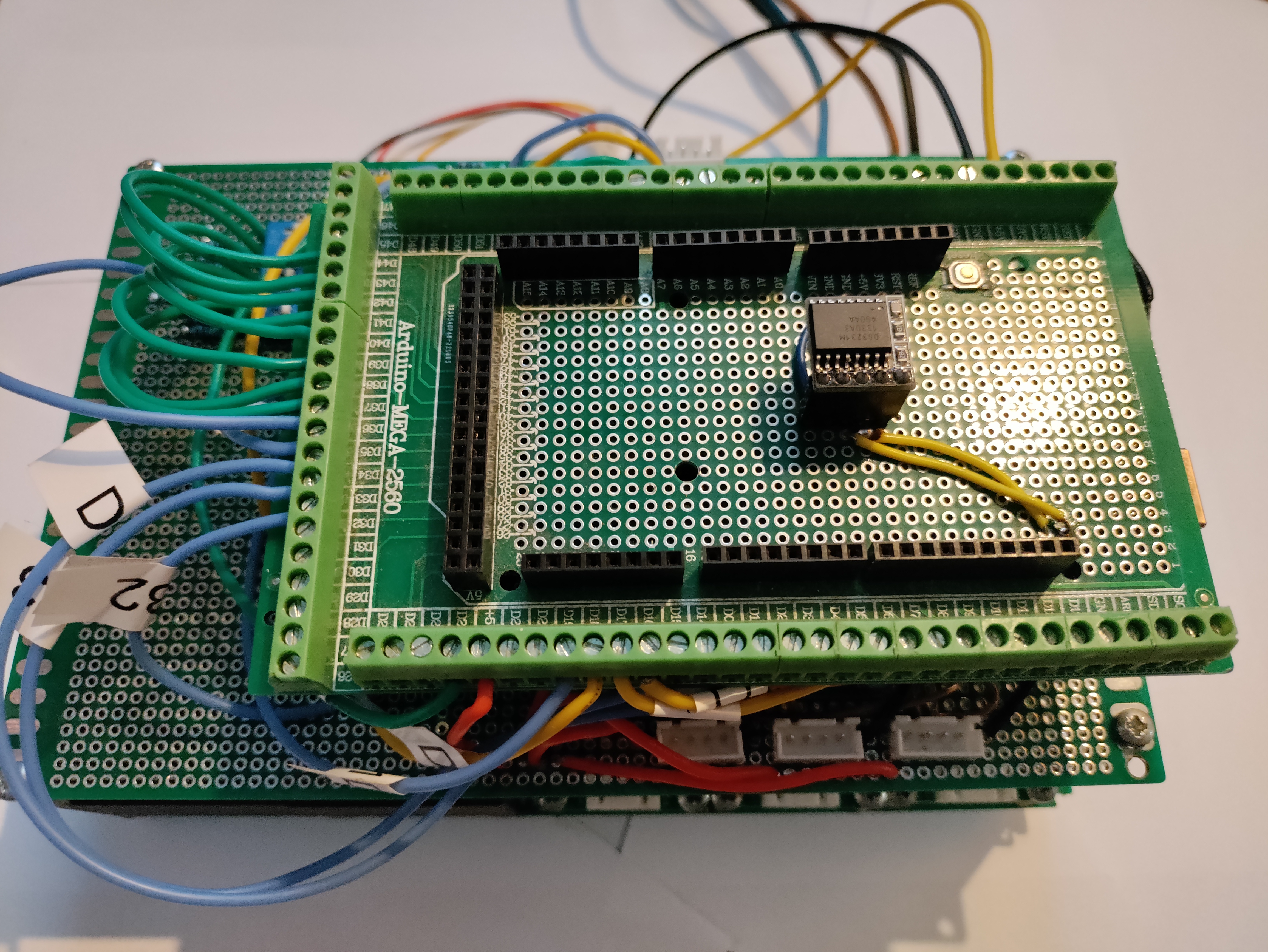
The main controller is an Arduino mega 2560 it is on a separate mezzanine board than the HV parts / PZEM Modules.
The ADG333 IC allows routing a single hardware serial port to the three PZEM modules. Querying is continuous and sequential, With a polling interval of 333ms between each module, giving a net polling interval of 1 second.
It could be technically feasible to have all PZEM modules on the same RX/TX serial TTL pair, but that would need to ensure that the optocouplers do not overload the RX/TX current sourcing capabilities, and also would need a factory preset of the PZEM-004t V3.0 addresses. Note that PZEM-004t V3.0 itself is a Modbus device.
The server itself encapsulate telemetry queries and present the 3 PZEM-004t V3.0 as a single Modbus server device to the Raspberry Pi client, although with Modbus register addresses remapped.
Thus, it seems more adequate to use the same Modbus address on each module, and switch them using an IC switch like the ADG333.
Time keeping & Synchronisation
A real time clock (RTC) 3231 mini module is used to keep track of time and the synchronization is done over PLC / Modbus.
Modbus address encoding of the server is done through a 8 bit DIP switch encoder.
Software (Github repositories)
Most of the single phase functionality is POC tested.three phase hardware testing and hardening is still in progress.Software is still in POC phase. Consider the code to be in alpha stage.
https://github.com/rodv92/PMTR_001_SRV
https://github.com/rodv92/PMTR_001_CLI
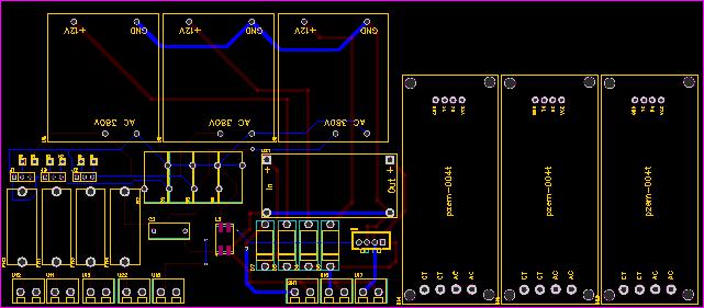
Hardware Schematics
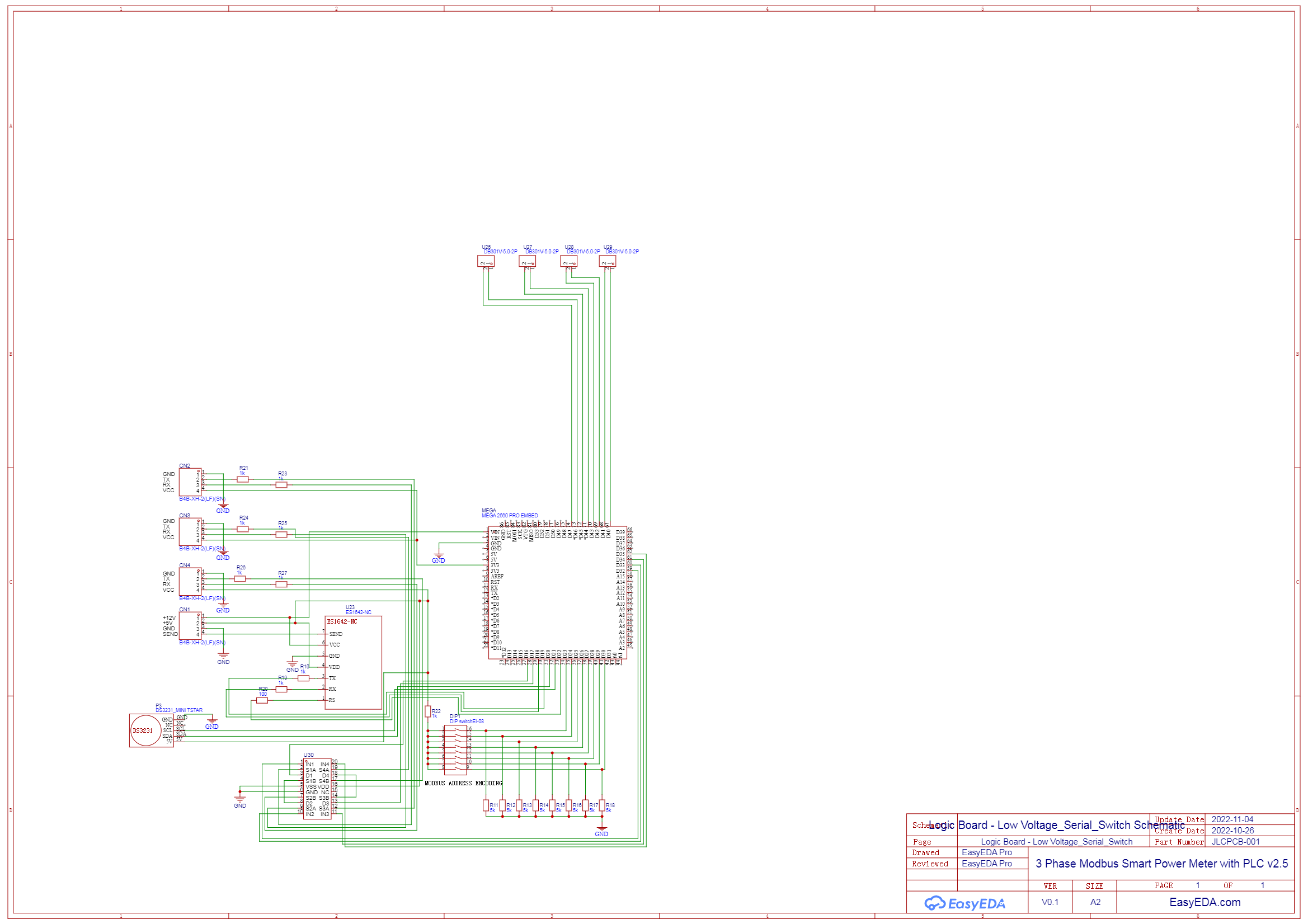)
This is the logic mezzanine board.

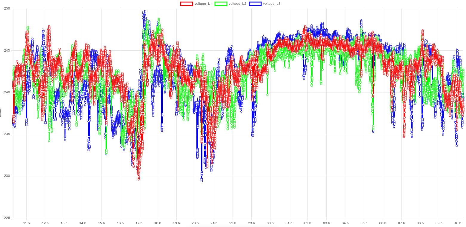
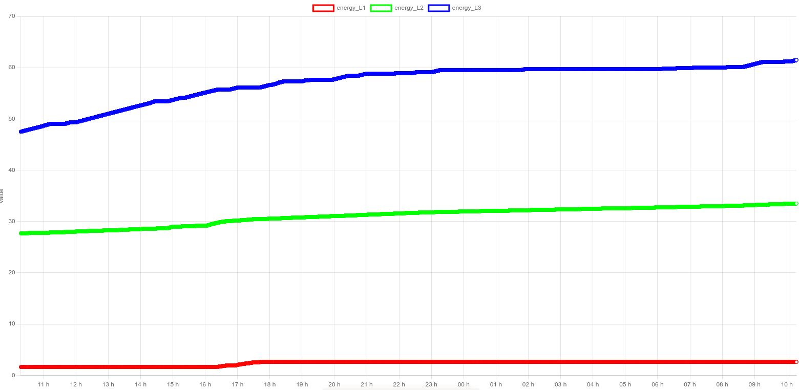
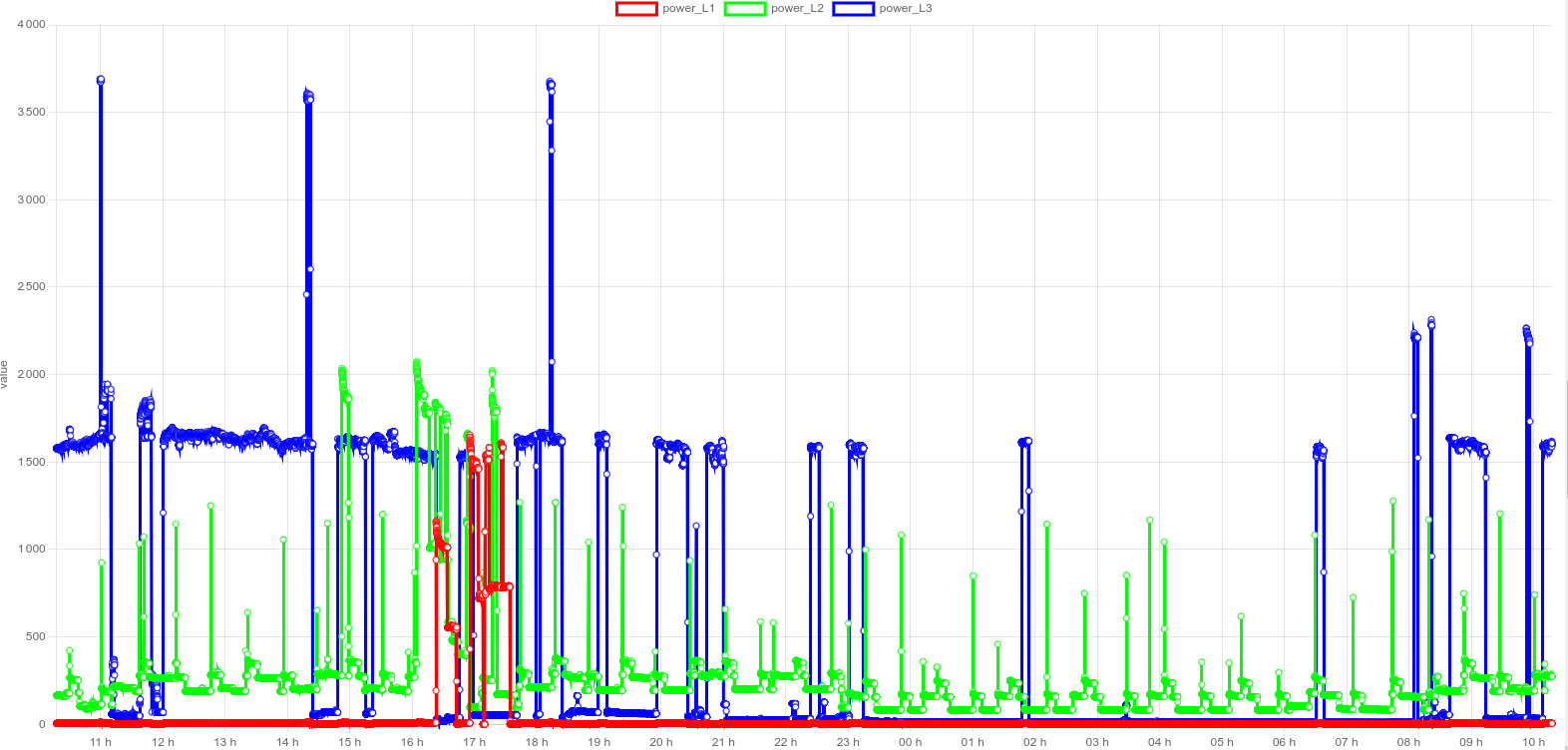
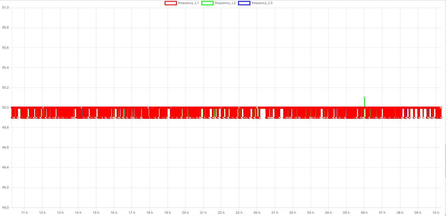
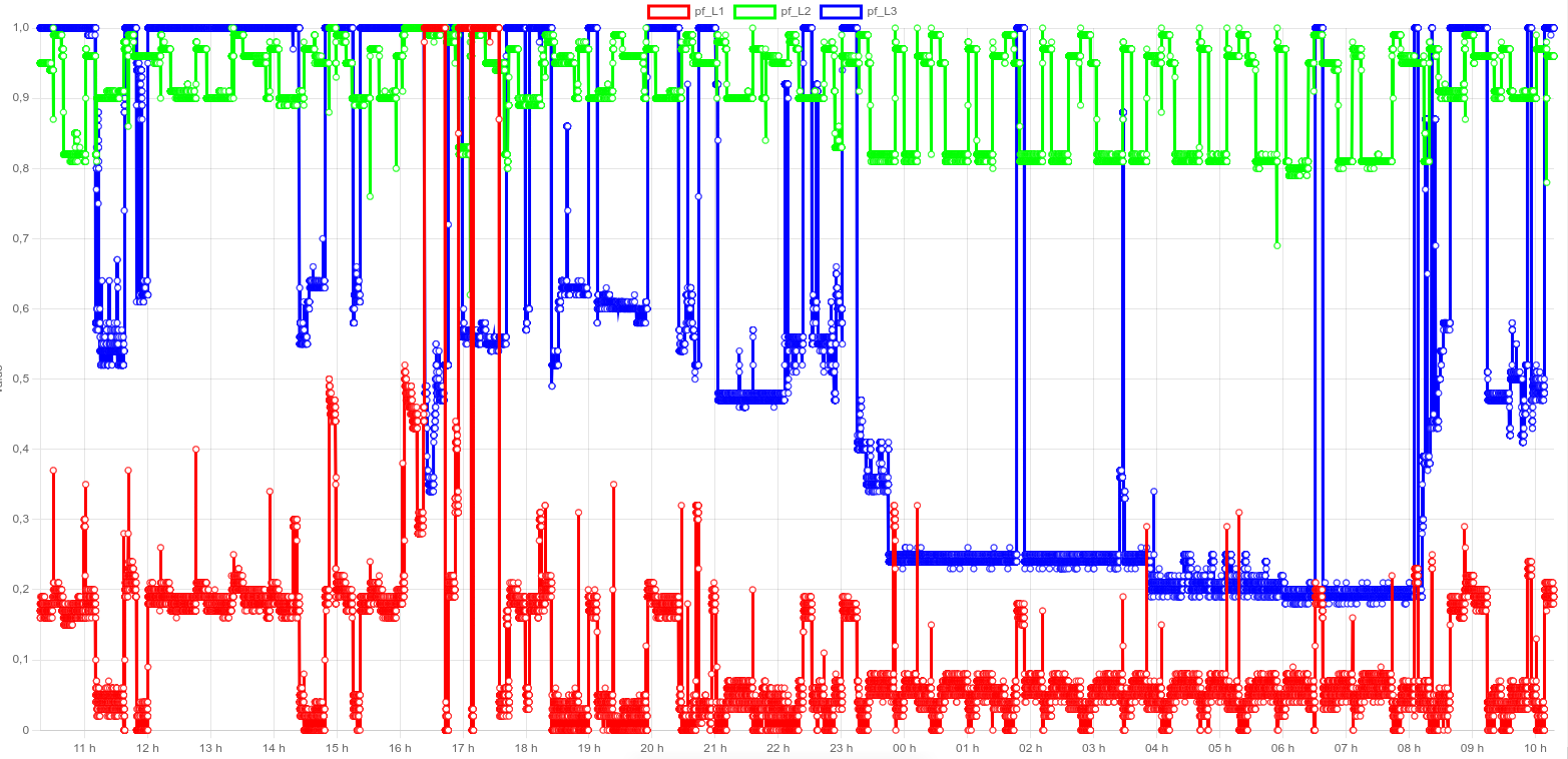
Client logger chart examples
There are chart.js Charts. Needs a luxon datetime adapter for proper datetime abscissa processing and display. All datasets charts represent the same 24h time interval.
Software library includes & Credits
Thanks to the Electrolab hacker space for providing me working room and resources to complete the prototype of this project.
Modbus library used for PLC client/servers communication
ArduinoModbus depends on the ArduinoRS485 library :
Specific modbus conditioning and parsing library for the power monitoring modules :
https://github.com/mandulaj/PZEM-004T-v30 by mandulaj
library for timekeeping :
https://github.com/PaulStoffregen/Time/blob/master/TimeLib.h by PaulStroffregen
library for scheduling task by timer ISRs :
https://github.com/khoih-prog/TimerInterruptby khoih-prog
library for parsing math and logical expressions (for relay logic) :
Leave a Reply