Photovoltaic array supplying an AC 230V water storage heater through direct boost conversion : Ltspice model with P&O MPPT.
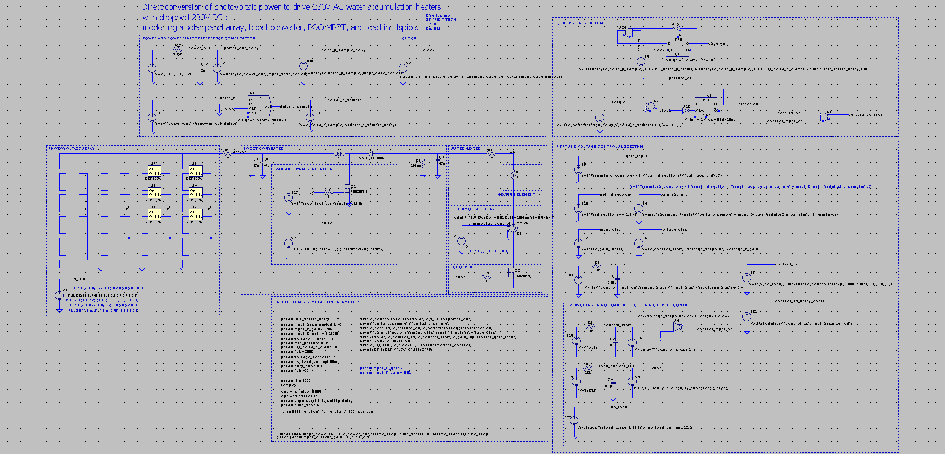
Download of Ltspice model at the end of the present article
Disclaimer
This article presents a a digital model of a water heater powered by solar panels. It is intended for analysis, teaching and optimization. Any practical model design and build based on this model can involve damage to property and life, from electrical high voltage hazard, fire hazard, water damage, steam release, and other non-specified hazards. Such designs and their installation should be done by qualified engineers and technicians, in a controlled environment. We are not responsible for any damage, loss, or injury arising directly or indirectly from any implementation based on the content of this article.
Incentive
Domestic water storage heaters, with their nominal power in the 1kW to 2kW range, are a good target for a dump load of any renewable power source. We will investigate the most efficient conversion, bypassing the need for an UPS, while preserving the MPPT power gains, and allowing seamless connection through a chopped DC power output (duty cycle 0.9, f=400Hz) as a means to ensure safe operation of the bimetallic strip thermostat protection in terms of current interruption. We will also investigate the potential benefits of photovoltaic direct conversion compared to solar thermosiphons and other solar heaters, which are the standard way of harnessing solar power to heat water in many countries.
Comparing thermosiphons and photovoltaic direct conversion
| Photovoltaic Array | Thermosiphon | |
| Material cost / kW | low | moderate |
| Surface area / kW | high | low |
| Installation complexity & speed & cost | low | moderate |
| Mechanical load / surface area | low | high |
| Maintenance | low (cleaning dust) | moderate (limescale formation) |
| Durability | 10-20 years | 10-20 years |
| Wind effect on efficiency | absent | slight decrease |
| Low Ambient temperature effect on efficiency | increased efficiency | decreased efficiency |
Considering identical material and installation costs, a photovoltaic setup may provide higher power, but two to four times the used surface area, and the dispersed mechanical load is at the expense of higher wind loading.
higher mechanical load for a given surface may also be a concern, since a collection tank is usually installed on the roof premises.
Limescale formation, and corrosion in steel based tanks require periodic maintenance and downtime, to a larger extent than for photovoltaic arrays.
As for meteorological conditions, high irradiance / high altitude climates (such as desert plateaus)
could be particularily suitable for photovoltaic water heating, since thermal losses (radiative and convective) would be higher on a solar water exchanger and outside collection tank, due to the lower overall ambient temperature (particularily at night for the tank) in such environments.
Photovoltaic designs are privileged here, since their power output is favorable at lower cell temperatures, and the source of power does not need to be in close proximity to the water tank, as it is for thermosiphons. This does not apply to pump powered systems, at the expense of complexity.
Anatomy of a storage electric water heater
Entry levels heaters, electrically speaking, are simple devices that rely only on a thermostat relay to set the water temperature and a resistive heating element, usually steatite encased nichrome or nichrome coiled wire in MgO and cladded in a stainless steel tube.
A sacrificial magnesium anode is usually present to reduce heating element galvanic corrosion on the heating element assembly in the case of nichrome/steel assemblies.
Any fancier water heater with digital electronics (ex : wifi connection and reporting) cannot be guaranteed to work properly on a DC PWM source, it may start, but its supervisory functions may not work properly on a DC source, particularly if it monitors the voltage input or power, and may prove a hazard. We do not advise to use these as a basis for any project derived from this article.
Adaptation of an AC water storage heater to DC power
Adapting such a setup to DC operation comes with a set of constraints and issues that need to be addressed :
- Ensuring that the thermostat relay, usually a bimetallic strip type, operates reliably on DC. The matter is complicated as these parts are usually intended to work on AC with their nominal DC parameters derated to a fraction of the AC operating voltage, when even present on the datasheet. This comes from the fact that the bimetallic strip takes advantages of the AC voltage (and current) zero crossing to safely interrupt the circuit when open.
- Ensuring that the conversion is efficient : The solar panel to water heating element power transfer must be optimized by matching impedance to the best extent. an MPPT algorithm is used to further extract maximum power from the solar panels.
- Provide RMS output voltage safeguards so as not to push DC voltage well above 230V DC, as well as not under 90V DC. ( so as the neon lamp indicator operates, as the striking voltage is usually around 90V. This under-voltage restriction however comes at a cost in terms of power extraction.
- Provide no load detection and stop switching setting the MOSFET driver to low in that condition, as any power converter would do. hiccup mode is not required.
The first constraint is usually addressed by chopping the DC output power so as to provide 0 volt off duty cycles.
The second constraint requires a DC/DC converter, and our design is focused on solar panel array constraints with a total OCV less than 230V DC, thus requiring a boost type converter.
MPPT will be simulated using a photovoltaic cell model derived from a commercial product and a control algorithm operating on the converter duty cycle.
The output of the converter will be decoupled with a 47uF electrolytic 400V capacitor mainly to recude EMI, that could be amplified due to the heating element parasitic inductance, and then add fixed low frequency duty cycle chopping (using a low side switching mosfet, interrupting the circuit) to provide 0V off duty to interrupt current, allowing the bimetallic strip thermostat relay to operate safely.
The third constraint is enforced by the comparing output voltage to a setpoint (typically 230V divided by the final output chopper duty cycle square root) which switches algorithm operation to voltage feedback mode (as would a standard converter)
Simulation.
Photovoltaic model
We will use Fesz (2022) photovoltaic cell ltspice model based on real dataheet data to simulate the solar panel array, Our model array is based on the SEP300W panel model.
I invite you to watch his videos for an introduction on solar panel dynamics and MPPT, as well as for Ltspice cell modelling.
the links for the SEP300W and other models are available in the video description.
Modeling Photovoltaic Cells – Theory 1/2
Modeling Photovoltaic Cells – LTspice model part 2/2
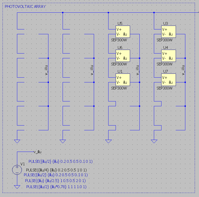
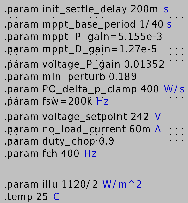
The model accommodates various serial/parallel arrangements, provided the voltage at MPP for typical illumination parameters do not exceed 230V * sqrt(duty_chop), typically 242V, or the converter will switch to voltage control mode, and will eventually stop switching, as it will not perform its intended function of boost conversion, and the load voltage will assume solar voltage (corrected by the chopper duty square root). Unless the chopper manages that situation, the DC RMS voltage may exceed the heater nominal RMS Voltage of 230V, as well as selected components voltage tolerances (set to a conservative 600V for MOSFETs and 400V for capacitors. This limitation restricts the number of panels in parallel.
As for series arrangement, the total I_mpp current may exceed the inductor, diode, and MOSFET, and capacitor ripple current specifications. This limitation restricts the number of panels in parallel.
Thus, we select a total solar panel number to obtain power immediately above heater rated power compensated for converter efficiency, we get n = int(heater_power/converter_eff)/solar_panel_mpp) + 1
We may get an odd number of panels, thus preventing a conventional arrangement, in that case, we add one more panel.
For a 1400W heater and 312W mpp SEP300W, we get a net number of 6 solar panels.
Giving rise to the following arrangements :
1P6S,2P3S,3P2S,6P1S.
The 1P6S arrangement would drive the output voltage, even at mpp, very close to the voltage control setpoint, thus rendering settling around mpp perturbed by handover to voltage control mode at full illumination. On the other hand, 6P1S woul exceed MOSFET specifications, and give rise to high inductor and MOSFET currents, and force the converter to operate mostly at high duty cycles
Thus only 2P3S and 3P2S arrangements are suitable for simulation, and allow testing the performance of both voltage control mode (typically reached at high irradiance when solar panel power output is higher than the load) and MPP at lower irradiance.
Irradiance modelling
V1 (v_illu) models the total irradiance in W/m². Using a PULSE or PWL file, we can model crude cloud transients. A typical cloud transient could settle in around 3 to 6 seconds (from nominal illumination to obscured illumination or vice versa), assuming an homogeneous cloud mass passes in front of the sun disk.
Converter modelling
For sake of simulation speed performance, we will use a simple, non synchronous boost converter topology. Monolithic converter ICs simulate slower, down to a factor of 10, and put emphasis on output voltage stability, and management of dynamic loads.
The digital control philosophy or this article also doesn’t fit well to the use of a monolithic IC.
While important, IC features, plus UVLO, ramp compensation, soft start, usually make simulation slow and are detrimental in the coarse tuning steps of the MPPT algorithm. Most of them will be eventually implemented in our model, but with coarser behavioral functions, that can simulate faster and nevertheless transpose correctly to a digital control model.
Simulation speed-up
reltol was set to 0.005 instead of 0.001 and abstol was to 1e-6 instead of 1e-12, These tweaks marginally impact simulation confidence, while boosting simulation speed by a factor of up to x4~5
The model simulates at around 3ms/s on a AMD Ryzen 3 PRO 3300U
Summary of the converter design constraints :
- Boost converter design
- Input OCV from 90 to 140V
- Output voltage restricted to 90V DC (chopped) RMS to 230V DC (chopped) RMS
- MPPT, as long as the output DC chopped RMS voltage is within above nominal parameters
- Low frequency (400Hz) chopping so as to provide safe operation for the bimetallic strip
- Adequate output bus capacitor filtering to reduce EMI to normative levels. ripple constraints are thus largely relaxed,
- No load detection
- Over-voltage detection and switch to voltage control mode
- Critical over-voltage detection even in the absence of switching and converter isolation at the solar panel level.
- MOV TVS protection at the solar input and solar output to protect the converter from fast voltage transients (direct or indirect lightning strikes, etc)
- Microcontroller driven : the MCU will drive a gate driver that will control the switching node MOSFET, as well as the chopper MOSFET.
- Power range : rated for 1400W power, corresponding to common power ranges for 50 L water heaters.
- Maximum duty cycle : 0.8
In that power range a standard, non synchronous, single phase boost converter would not be the most adequate design in terms of efficiency. it is however the simplest in term of model and simulation speed.
A real design that would transpose easily from that simulation model would be a two phase synchronous boost converter. A design using a diode based boost converter with single phase switching as presented here would need to be a scaled down. (keeping average diode current under 4A)
The algorithm is simple and designed with digitization in mind, so it will use behavioral sources, and whenever possible, basic Ltspice digital blocks (such as flip flops an gates to maintain the state)
Since voltage stability is not an issue besides filtering HF switching, and a lower/upper bound control,
a fast control loop typically found on converters that input the output voltage from a divider to a feedback pin and then to an error amplifier with a compensation network will not be present, except in the form of analog LP filtering at some input and output stages. If the variable duty PWM switching generation is to be performed fully digitally, some digital filter DSP logic should be implemented on the duty control signal.
A fully digital control loop requires some other protections, so as to maintain a fail-safe output voltage in case of a digital control failure, and quick reaction to over-voltage situations.
MPPT algorithm
Power is measured (either at the solar panel output, or at the converter output) depending if one wishes to factor in the converter efficiency at various duty cycle levels, and this may have an effect on the overall algorithm parameters tuning. Our design measures power at the output.
The fact that the load is constant, mostly resistive with very low inductance facilitates the design, as the sudden output power changes from steady state would mostly come from illumination transients.
- The Ltspice algorithm inputs are power output, as a product of voltage and current ( which is then lp filtered) and output voltage separately, as well as output current.
- The algorithm output is the commanded duty cycle.
Thus A practical digital control design would see a few adaptations from this Ltspice model, and use at least two DAC channels, one for current output and one for voltage, and derive power from these two inputs. More DAC channels could be used if the same input quantity needs to be LP filtered through analog means, using different filter parameters, and if one wishes to lower DSP burden.
A digital pin may be used to monitor the input of a schmitt trigger device with hysteresis to monitor overvoltage conditions and stop switching immediately through an interrupt, the same logic would be use to monitor load disconnection.
Power measurement
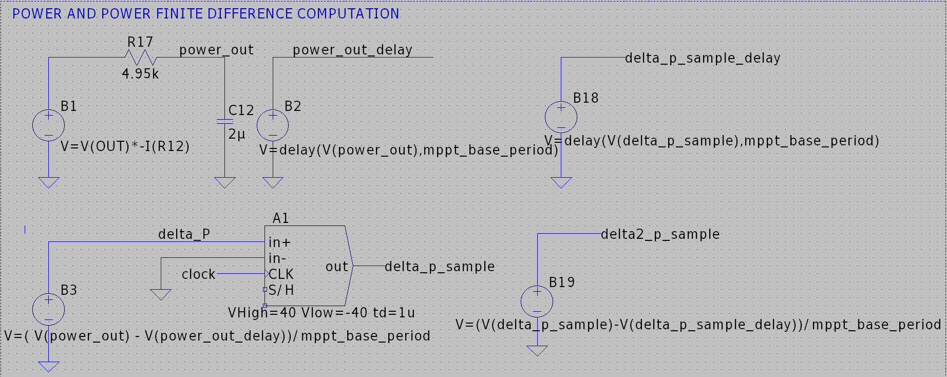
The power signal is generated by the behavioral source B1, and filtered by a lowpass
RC filter with a cutoff frequency of 16.07 Hz
The finite difference is calculated by delaying the filtered power signal by mppt_period, and then subtracting the delayed power signal, from the non delayed power signal, and dividing by the mppt_period parameter. Using finite differences rather than absolute differences allow us to display variations of power in W/s.
Using this approach gives us better control over the discrete time interval. As the use of inbuilt idt() is based on internal simulation time steps, it may generate high frequency spikes, that need subsequent heavy LP filtering, so we do not find it useful in our design.
Then, the delta_p signal is fed to a sample and hold block to output a sampled signal. it is not required in a Ltspice implementation, but matches more closely what a digital implementation would do and makes debugging and tuning the algorithm way easier through chart inspection.
The sampling rate, mppt_period in the sketch, will be used throughout the algorithm as the base period.
we chose a 40Hz mppt loop frequency, as it is a common speed used in literature and commercial products.
The sampled delta_p signal is represented by the voltage at the delta_p_sample node
This sampled signal is subsequently used to obtain the second finite difference in W/s²
represented by the voltage at the delta2_p_sample node
delta_p_sample and delta2_p_sample are then multiplied by their respective gain design parameters and summed, in the same fashion as a PID controller (the controller would be more aptly named here a derivative / second derivative controller, with respect to power output) proportionality to power here is impossible because the MPP, that would be the setpoint, is not presumed to be a known or even reachable quantity even in the presence of an illumination probe, though such a probe usually ease tracking.
The second finite derivative is mainly used as an attempt to ease the detection of the MPP.
Since we use a proportional/derivative control perturbation, and not fixed duty perturbation, the controller may stall its tracking since the duty to power loop is not linear, imparting too low duty cycle changes to give rise to meaningful power changes, for this case, we add a floor to the perturbation, namely, min_perturb.
Perturb and Observe cycling algorithm
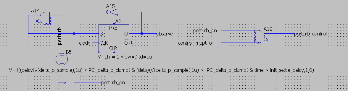
Digital pacing and control lines then manage the perturb and observe period, as well a duty cycle perturbation direction.
The logical block around the A2 flip flop generate alternating perturb_on and observe cycles when the controlling perturb digital signal is high. The master signal perturb is logical high when the delta_p_sample is within parameter bounds (-10,10) to prevent the controller from working to compensate fast transients (very fast cloud transients, airplane transits, etc). an initialization delay, init_settle_delay has been added to allow the converter to reach steady state at startup.
When perturb is low, both observe and perturb_on lines are low, halting the algorithm operation, until power variation gets back into nominal bounds.
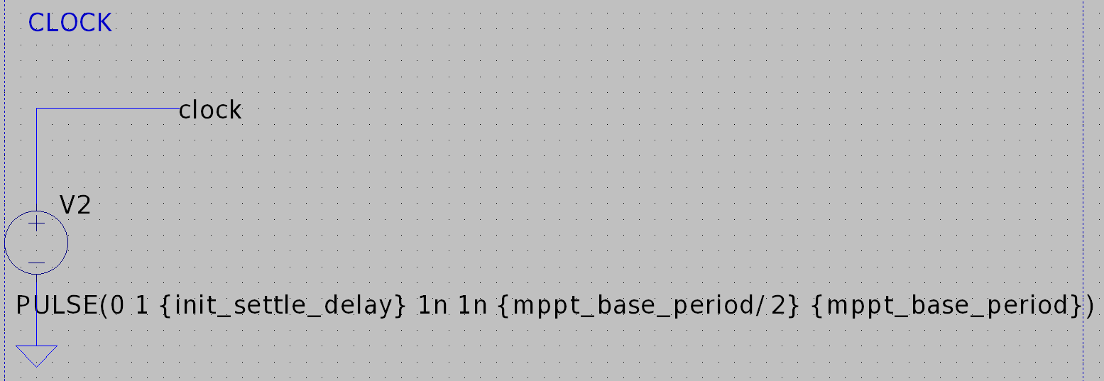
clocking is performed by a PWM source of period mppt_period
Perturb duty variation direction control
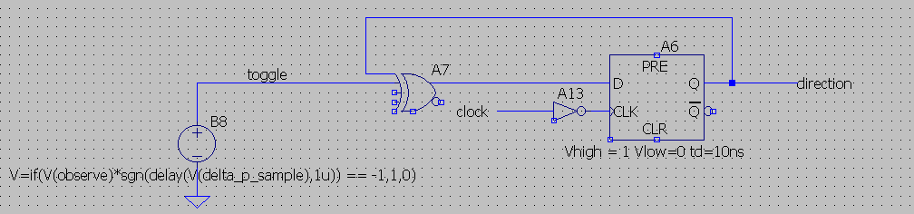
The logic block built around A6 manages the direction of the duty cycle perturbation
if the product of V(observe) and the sign of V(delta_p_sample) is negative, a toggle pulse appears.
This pulse toggles the direction logic node, that will be used in subsequent algorithmic steps.
MPPT duty gain computation algorithm and duty perturbation integration
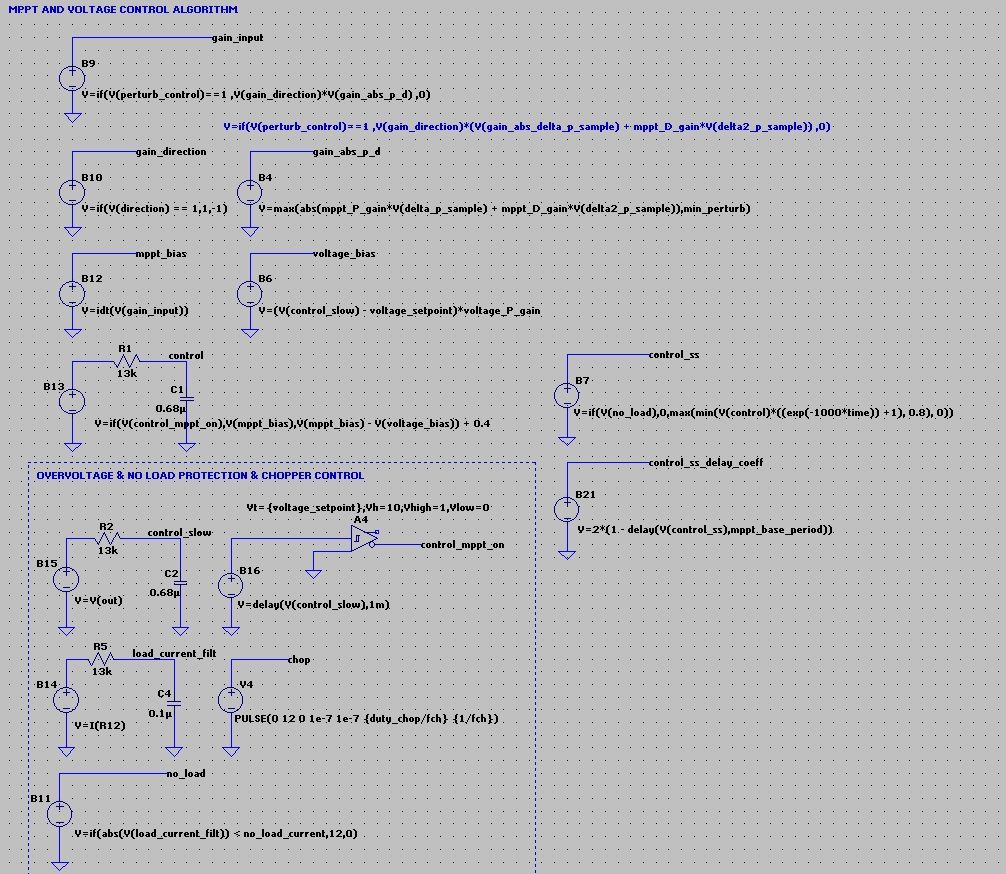
B9 computes the duty cycle perturbation amount using the derivative/second derivative of power controller gains, multiplied by V(gain_direction).
B10, outputing V(gain_direction), simply converts the logic signal V(direction) into a two state (1,-1) signal.
B12 finally integrates the duty cycle perturbation signal V(gain_input) into V(mppt_bias), that will form the basis of the control signal V(control). It also manages voltage control mode handover when the the control_mppt_on signal switches to low.
B7 multiplies this signal by an exponential function to obtain a soft start operation during switching initialization at controller startup.
B17 and V7 together generate the gate driving variable duty PWM signal, with a gate voltage above ground compatible with the selected MOSFET.
Overvoltage detection and management.
Tracking mppt may push the output voltage above the 230V DC nominal voltage for the water heater, This mostly happens when the total nominal power of the solar panel arrangement (the sum of individual solar panel nominal power) is greater than the water heater nominal power, in high irradiance conditions, and with high parallel arrangements, where the commanded duty is under 0.8 to reach 230V DC.
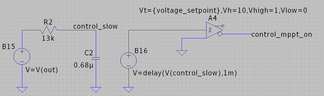
In an over-voltage situation, the controller must switch from MPPT to simple voltage feedback mode, managing duty cycle as not to exceed 230V DC output, reverting to MPPT mode when commanded duty is unable to maintain 230V DC. Hysteresis with Vt=242V Vh=10 is implemented using a schmitt trigger (A4).
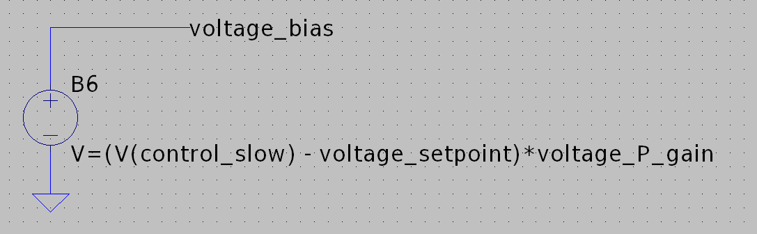
B6 computes the gain input in voltage control mode.
It could be tempting to implement analog / voltage divider feedback as a means of failsafe voltage control mode for overvoltage and MCU failure conditions, but the handover back and from digital and analog control is tricker to implement.
So, a schmitt trigger solution that is linked to an interrupt seems way easier to implement and safe enough.
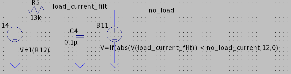
There is also another mode where high voltage in the output can arise, this time more prominent in high serial arrangements, when the commanded duty cycle is high. If the load resistance drops to 0, as it is the case when the heater thermostat trips, and switching does not stop immediately, the voltage spike at the inductor gets transferred to the output capacitor bank, and may rise its voltage well above 230V DC.
Overall, switching should be stopped as fast as possible in a load disconnect condition, using the MCU emergency PWM stop provisions, usually interrupt driven, the source of the interrupt should be a logic signal that is tied to the current sense shunt resistor voltage, using a schmitt trigger to switch logic states when the sense resistor voltage drops to very low values. (Corresponding to 1/100 rated current in our design).
The final over-voltage trivial condition arises for improper installations, in high serial arrangements when OCV is above 242V DC. switching may counter intuitively reduce input voltage and towards MPP, but the algorithm is tailored to manage these starting conditions in voltage control mode. We have to remember that this is a boost converter after all, and the input voltage range (from MPP voltage to OCV) should stay well below output voltage. In that condition, the converter should not only refuse to start switching, but also isolate itself, turning itself off once the MCU capacitors discharge beyond designed hold time. This protection is not modeled here.
A MOV may be implemented to prevent the capacitor voltage to rise above the rated electrolytic capacitor voltage, for highly abnormal conditions, or lightning strikes, for the latter, MOV protection should also be implemented as close as possible to the solar terminal inputs. High voltage, high capacitance electrolytic capacitors submitted to voltages over their ratings may burst with a considerable energy release. So this risk should be seriously taken into account.
Internal fuses are not modelled, but any practical design should implement them, and DC external fuses selected and installed according to code should be installed in any solar setup.
The output capacitor should be rated for 400V or more.
Also, a high value bleed off resistor should be implemented in parallel to the capacitor to discharge it, so any maintenance is performed safely. Such a capacitor also assist in mitigating transient over-voltages.
For this application, we will use a 1Meg bleed off resistor.
Final output chopping
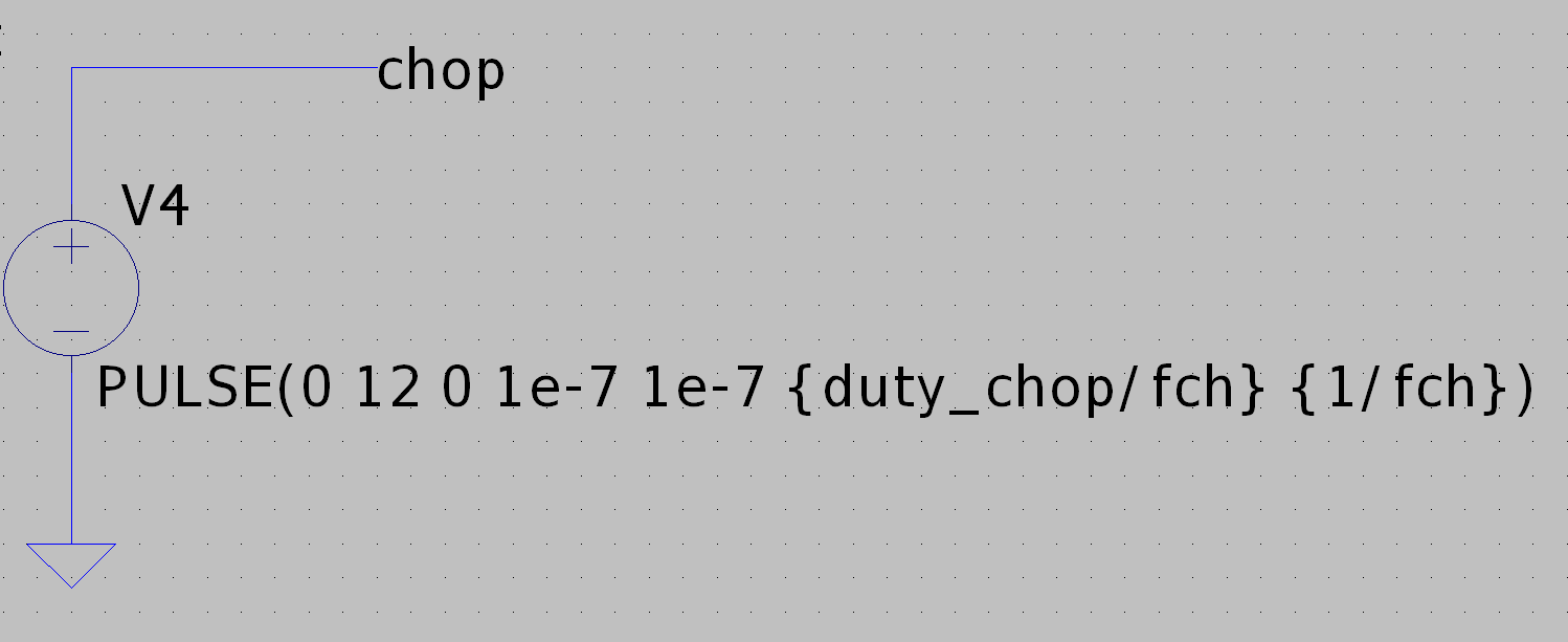
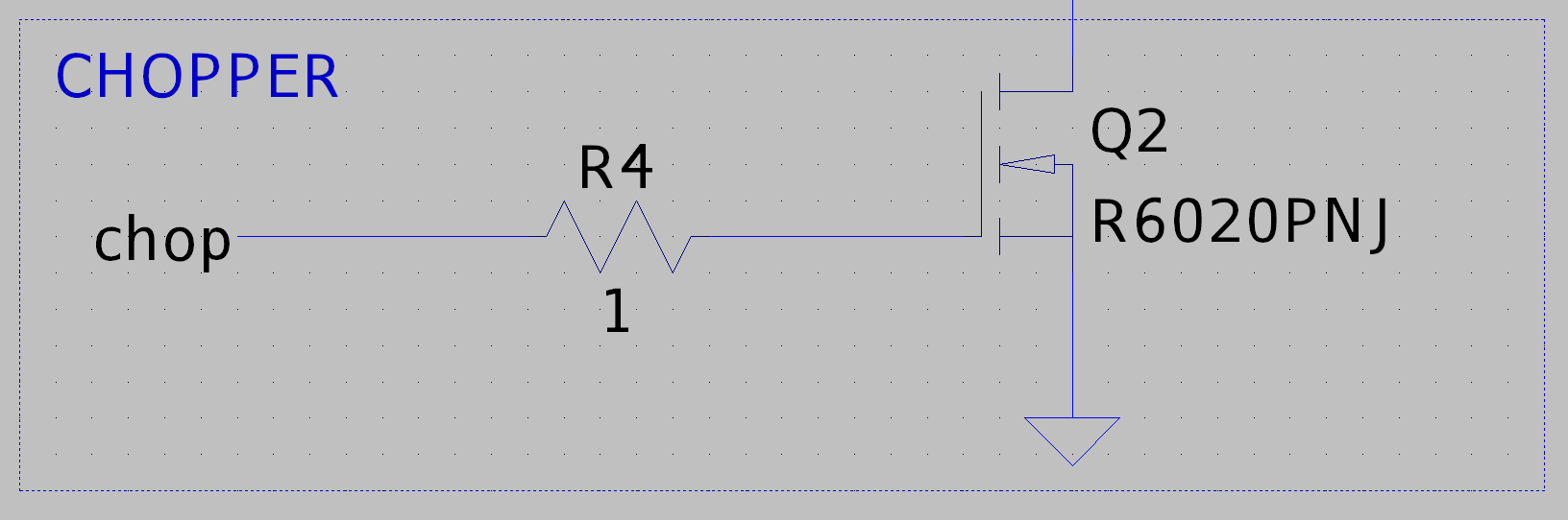
A low side swtiching MOSFET is used to periodically disconnect the load at a moderate switching frequency, such as 400Hz and a duty cycle of 0.9, to provide 250us of 0A current in order for the thermostat bimetallic strip to open in a safe manner (quenching any arc in a timely manner) when it triggers.
As a disclaimer, this design step is particularly important. It cannot be guaranted that the thermostat will operate at 400Hz PWM DC with a duty cycle of 0.9 safely without a fire hazard risk. A careful analysis of bimetallic strip dynamics and arc quenching should be done, but it also cannot guarantee that the thermostat will behave safely, due to the lack of datasheet parameters concerning the strip geometry, and variability of designs that the firmware cannot account for.
Thus, any serious design would probably involve a retrofit kit to replace the thermostat relay with a thermometer probe fitting into the water heater thermowell and manage the water temperature through the firmware control algorithm. A safe relay can then be integrated into the solution, or make use of the chopper MOSFET to swtich the heater off. Provisions should be taken for probe dysfunction, as water overtemperature will give rise to pressure rises and trigger the water safety relief valve or damage the heater and may cause steam explosions.
load disconnect simulation
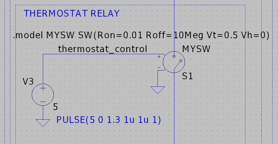
S1 switch simulates the thermostat relay bimetallic strip, in order to monitor proper converter
when the load is rejected.
Powering the MCU
Since this is a battery less design ( a small mAh Li-ion rechargeable cell could be implemented) and the input voltage may still be quite high for linear converters or even step down converter IC modules, and we do not need much more amperage at 12V than a 50 to 100mA, a cascode MOSFET arrangement could be sufficient to bring the voltage to a safe range for one 5V or 3.3V linear regulators, plus one regulator supplying a 12V rail for MOSFET swtiching. Suitable MLCC and electrolytic capacitor should be implemented for filtering and hold time. This is not modelled here.
Parameter space
Performance Charts
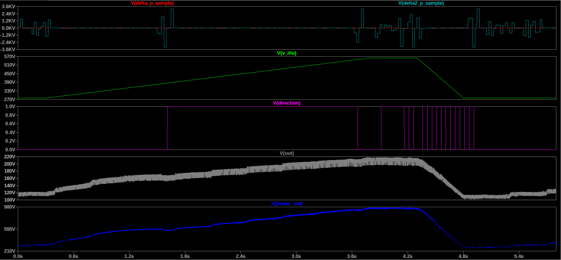
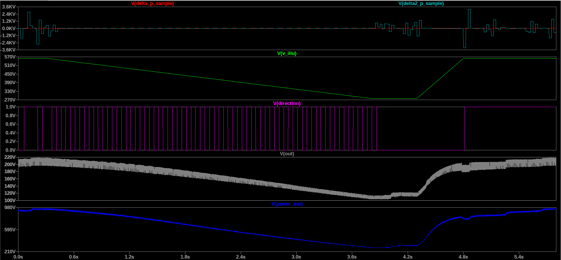
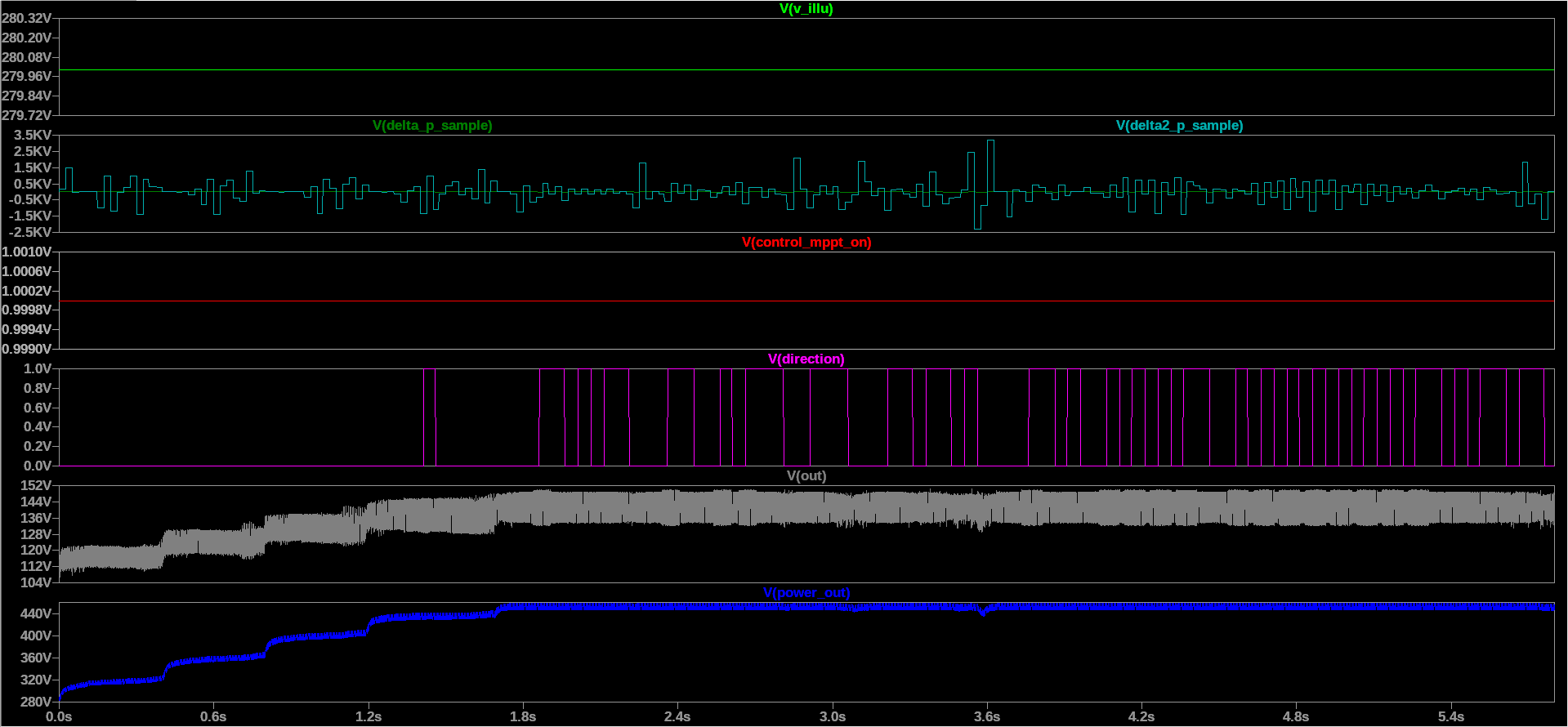
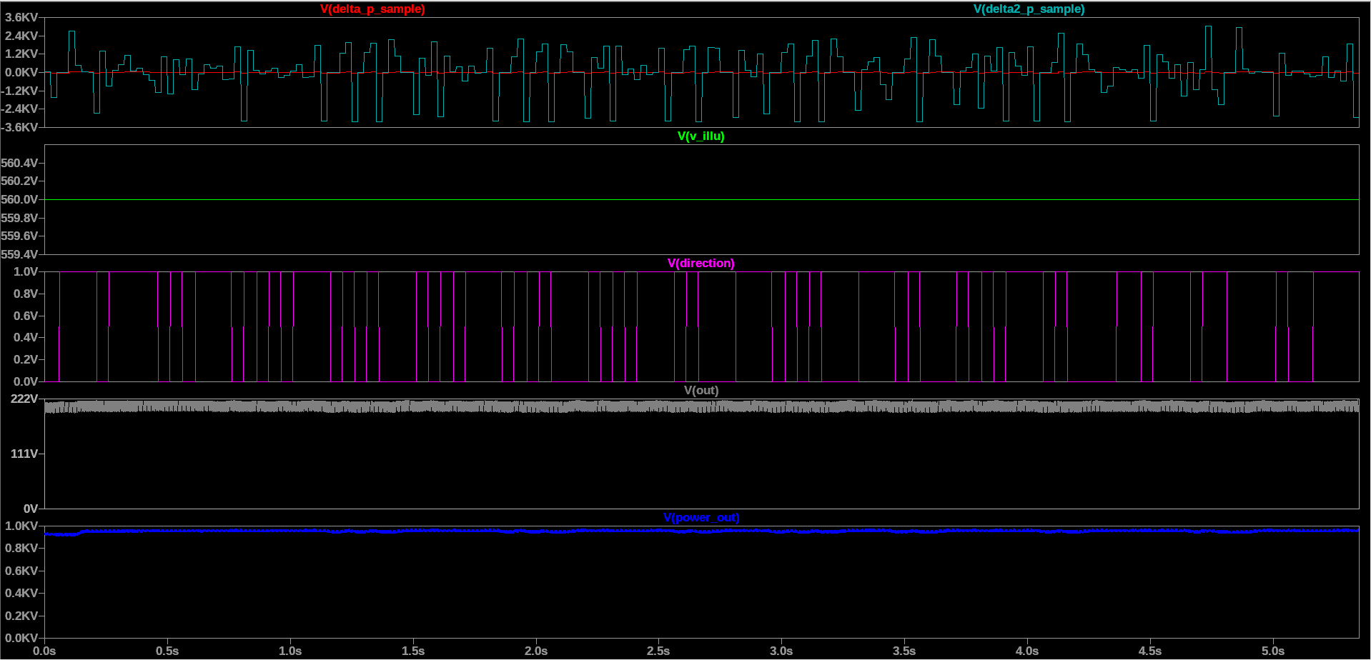
MPP tracking is consistent with datasheet published MPP parameters (multiplied by the number of solar panels in the array), using interpolation to determine the MPP at 280W/m²and 560W/m² (respectively 77.79W and 170.16W per panel). During steady state periods, the output power is stable, with spurious, fast damped oscillations, with oscillation amplitude less than 5% output power. Convergence to MPP is obtained in a timescale of a second to a few seconds. The difference between theoretical MPP and measured RMS of power output mainly comes from converter losses. (converter efficiency ~0.9)
MPPT to Voltage control mode handover
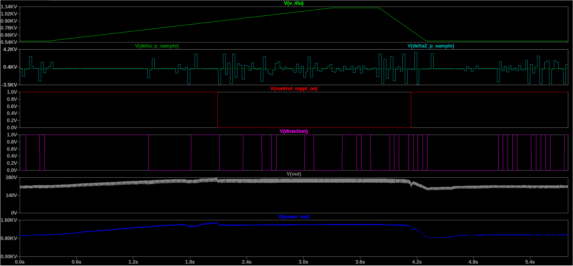
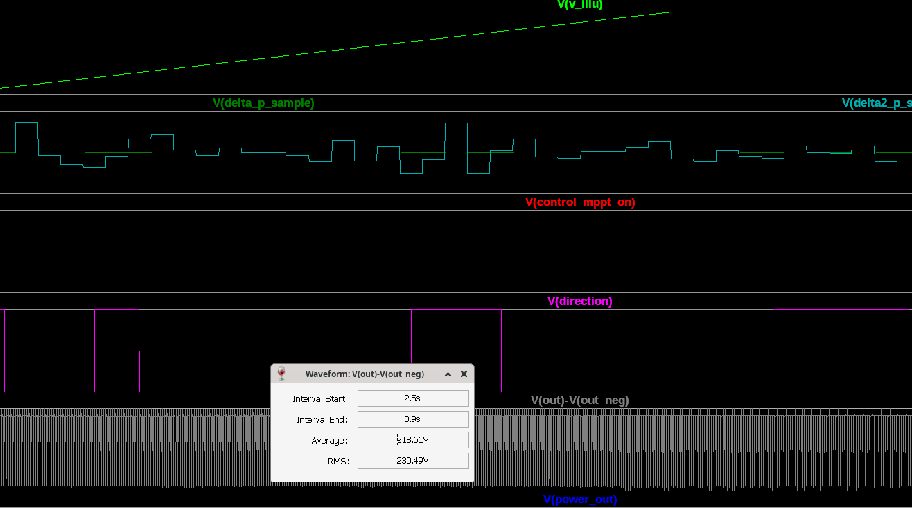
Conclusion
Parameters have been optimized empirically.
A rigorous mathematical analysis may be done in the future and would be followed by an update of this article.
There is considerable room for improvement, but the model has proven quite stable with moderate and damped oscillations with a time constant negligible in comparison to typical irradiance transients.
Note that the transients modeled are fast ones compared to typical cloud transients, and these transients
are described using simple ramp functions. A detailed analysis using real, stochastic data would take considerable simulation time.
At that point, its better to use a physical scaled down model and a controllable light source to optimize the final design.
As for a larger field of application, MPPT boost conversion would prove rather useful for a whole range of 230V rated ohmic dump loads, as the boost conversion allows better impedance matching, permitting the power source, whether photovoltaic or wind turbine, to operate in its MPP regime for the dump load.
A market suited converter would also provide classic buck conversion, to account for the thermostat trips when temperature has reached its setpoint, thus using either separate buck boost units, or buck/boost converter design switching its outputs between a battery and the dump load.
Whether the water heater is considered as the dump load, and the battery charging as the primary function or vice versa is a design choice, but could also be a device setup parameter.
Finally, the converter could also implement an ATS to seamlessly integrate the dump load into mains power, in low photovoltaic or wind power levels.

Leave a Reply