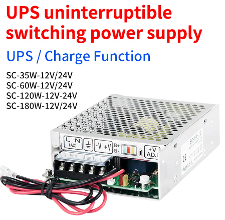
SC-120W 12V PSU with UPS function review.
or How to battery backup your router the proper way.

This unit is a good choice to provide long UPS time in an event of a power outage for small but critical loads like an Internet router, Where a full 110V/220V UPS is overkill. A typical internet router power rating is around 15W. Assuming the SC120W is wired to a 60Ah 12V battery and assuming 50% discharge, the router could keep working for almost 20 hours in an outage event.
Voltage Setup.
There is a white screw near the battery cable. This regulates two outputs:
- The set float voltage of the battery (for a lead acid battery, this should be always set up at at least 12.9V +/- some voltage according to the ambient temperature, but it will be always more in a realistic scenario, the float voltage is between 13.1V and 13.8V. That means that this unit is not made for frequent outage cycles, since it would also cycle charge the battery, and charging is usually done at higher voltages.
- This screw also regulates the working voltage of the load, minus a diode drop it seems (that is, the load voltage will be the battery float voltage minus 0.6V)
So, for example if you set the battery float at 13.8V, the load will be supplied 13.2V. Routers have voltage regulators inside. As a rule of thumb, electronics tolerate +/- 10% deviation of the nominal supply voltage which is 12V for most routers, Putting 13.2V into the router could damage its regulator over the long term, leading to reduced lifespan.
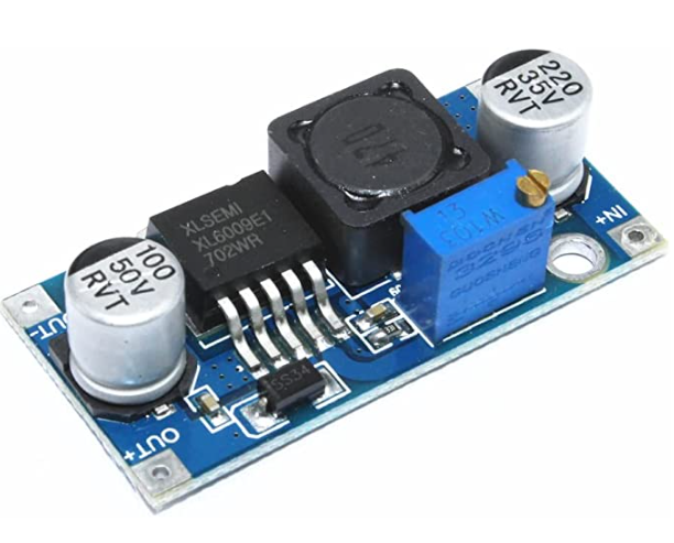
The proper way to do it : Insert a DC/DC step down module like these based on the LM2596A between the SC120W and the router,

and adjust the step down module to output 12V, now you can set up an appropriate float voltage for the battery without damaging the router.
Charge current limiting.
There are no regulating screws for charge current limiting, so, if you set the voltage too high and the battery is discharged, it could draw current up to the overcurrent protection limit. I did not push the test unit far enough to see if it is 10A or less at (the PSU nominal power rating), Nevertheless, it is recommended to charge a battery at a current no more than 0.1 * total capacity. If you use a small battery, and there are some outages, reduce the float voltage accordingly. Best is to use a large battery so you can setup a higher float voltage, its lifetime won’t be affected by the charging currents which would fall mostly under 0.1 * total capacity, and it will benefit from higher float voltages.
Optional setup for frequent and long outages.
In case of frequent and/or long outages It could be theoretically possible to use a dedicated battery charger to charge the battery using a bulk charing constant current phase, a topping charge, and a trickle charge phase commonly used in “intelligent” chargers, in addition to the SC-120W. This would be done by connecting the battery terminals to such a charger, and a diode between the SC-120W and the battery, to prevent the SC-120W from backfeeding the battery, that is, current flow would be restricted from going from the SC-120W to the battery, only allowed from the battery to the SC-120W. Charging would be performed only by the added dedicated charger. Such a charger should be a model that allows for continuous use.
Overall, it would serve to protect the SC-120W from having to deliver large currents to charge the battery up to its nominal capacity after a long outage where the battery is deeply discharged.
The downside of that setup would be the additional voltage drop from the diode between the SC-120W and battery while operating on battery, as it could bring the voltage into levels below 12V
Ideally, the voltage setting of the SC-120W would have to be setup so that it is more or less the same of what the charger voltage is at its max value minus the voltage drop of the diode, and that is program-phase dependent, To complicate issues more, the voltage drop of the diode also depends on current. Some chargers output high voltages for short periods of time in the equlization phase. Best is to have a good charger datasheet that explains well how the charging is done and allows for a good amount of configuration. Having voltages more or less equal could help in the regulation of the SC-120W. As the circuit of the SC-120W is not published, it is hard to say what would be the behaviour of the unit if it is setup at, let’s say 13.2V and a charger outputs 14.4 V, the SC-120W would then see 13.8V (accounting for the voltage drop of the diode added between the battery and the SC-120W), while its setpoint is at 13.2V
I encourage you to perform extensive and careful testing if you wish to go this way.
Behaviour while in UPS mode.
Voltage regulation behaviour testing should also be performed when the unit is on battery (without AC). Unfortunately, I lapsed to note data from this part in my testing protocol. If I remember well, the voltage seen by the load is then the battery voltage minus a diode drop. That is, the SC-120W does not perform dc step-up conversion to keep the voltage at the setpoint of nominal operation (on AC) Again, this should be tested, as designs may change over time. I will update this material when able to perform the test.
Behaviour on battery power loss / cold start mode
One peculiarity of the unit : If the battery connection is lost during a power outage, and is subsequently regained while the outage remains, or if the unit is connected to a battery to supply a load while it has no AC power, the load will not come online again by itself. There is a little button near the voltage potentiometer that will force supply power to the load, this function is known as a form of cold start.
It may also be possible that this function activates if the battery voltage falls under a certain level, to protect the battery. but I have not tested it.
LED indicator strip
There are three LEDS, on a strip connected to the unit through a ribbon cable. This is practical for industrial front panel installation.
- One shows that AC is available (red LED)
- One shows that DC power is supplied to the load (green LED)
- One shows that current is flowing between the SC-120W and the battery. (red LED) It glows brighter under high current conditions. I suspect this is the “battery is charging” indicator. When charging current settles down, the red LED light slowly turns off. I have not tested if this LED also glows when high current is drawn from the battery.
A final warning.
The battery cable of the SC120W does not have inbuilt fuses. It is always required to implement fuses on battery links. Add a section of cable with male spade connectors (the SC120W battery terminations use female spade connectors) with a fuse in it.
Overall rating.
The unit is sturdy and the UPS function performs very well, (for over a year) and it charges/discharges the battery as advertised. There is 0 downtime during switching events. The only down sides is that is a CV control mode only (no constant current charging phase) and that the system load voltage is related to the float voltage of the battery, Given the price of the unit that’s overall worth it.
There is also a 180W unit. This could also proove a good choice to provide battery backup to larger DC loads like NAS appliances, Beware, some units require a dual +5V + 12V psu, replacing that PSU by the SC180W would require two instead of one, higher rating DC/DC step down converters.
Leave a Reply