Design and fast prototyping of a milk curd stirrer and heater using Arduino.
December 2024 Update :
Present project has been amended with the addition of a buzzer to warn of temperature overshot. It is very useful to prevent milk spills in high temperatures processes pasteurization / sterilization steps.
Also, variable stirring duty cycles support has been added. This is useful for process such as milk jam preparation.
Note that such processes (such as milk jam production) are evaporative. An airtight electronic enclosure is required to prevent condensation, forced air flow over the enclosure and motor helps prevent this occurrence and enhances evaporation.
The best option is to connect a steam tolerant extractor and add two covers attached to the main plate with one exhaust port on one of the addon covers.
Foreword.
This project adhere to the DIY/maker ethos and use a fast prototyping, modular electronics approach.
It also demonstrates that a project can be done even without all the ‘proper’ tools, situations that are encountered
every day in workshops of less developed and fortunate countries, or simply in bad luck situations or when working in a secondary workshop that is not well furnished.
Some tools are non negotiable, but at other times, all it requires is a little inventivity, a bit more skill, patience and the zen spirit.
This is my first true project involving mechanics and electronics. I consider myself with a bit of experience under the belt in electronics, more experience in MCU coding, although
my code is crap before I decide to clean it up and properly factorize (which takes a long time to be put in motion) specially when i code in a rush (that was the case in that project).
I’m sorry for that.
As for mechanical engineering, I am an absolute beginner.
For the thermodynamics aspect, a little research online helped quite a lot.
There are overall a lot of lessons learned and practices confirmed to be important in completing a somewhat complex DIY project.
The more important are, in my case were :
For the idea to proof of concept part, check for state of the art using online resources, specifically video advertisements of similar devices, and see what features you can keep
from them. also check other makers work, and apply the Japanese philosophy of making an already existing product better if you dare.
careful beforehand planning of operation steps. write things.
Ordering of the operations so they don’t conflict each other and make another step impossible because of oversights is the most difficult part, at least for me.
CAD is advised to have a virtual look at the project and is good for post project documentation, although it takes time, and won’t be of real help
if you don’t use machining shops in your project.
May be useful in the future though if you decide to produce more, and also as an advertising and proof of seriousness in your endeavor.
Document your project during execution of the machining, packaging, and all the ‘practical’ work. it will serve you later by giving you a precise
view of the challenges you encountered, so that you can refine the production cycle through continuous improvement. sometimes a picture may be enough.
Video is paramount if you want to make your project public for other DIYers, and advertise it. It is hard to find the time to take pictures or videos when you’re in
the flow doing shop work, because it may break that flow. take it as a break time. making the video useful by being always centered on the work area is the big time cruncher.
In these cases, pictures are a perfect compromise.
Take inspiration of the hackaday like sites to see how experienced makers and hackers document their project.
analyze f***-ups in detail when they happen (root cause analysis, including psychological factors that lead to the mishap) so they don’t happen again
assumptions are the mother of a lot of them.
a great part of the skill required comes from an intuitive feel of Newtonian physics in the conception phase, and dexterity in the shop phase.
Look at a lot of DIY and shop videos to learn skills you don’t have beforehand.
compile the CAD files for parts and from the electronics EDA tool so that your BOM is comprehensive, and order more than required for cheap parts, especially if sourced
from China. sourcing skills are also something you’ll need to work on, and also it is quite fun to browse marketplaces when it is not for mindless consumerism.
Good luck to you !
1) Presentation.
milk curd stirrers are one of the critical devices used in the dairy and cheese industry.
A professional device usually performs these operations :
- Precise control of heating (heating slope and temperature hold control, multi-step heating)
- Stirring
- Curd cutting using a cutting grate.
Some devices implement passive or active cooling using a refrigerant coil.
Professional devices are usually large, several hundred litres devices in the entry level market.
This scale is not suitable for small family farm operations.
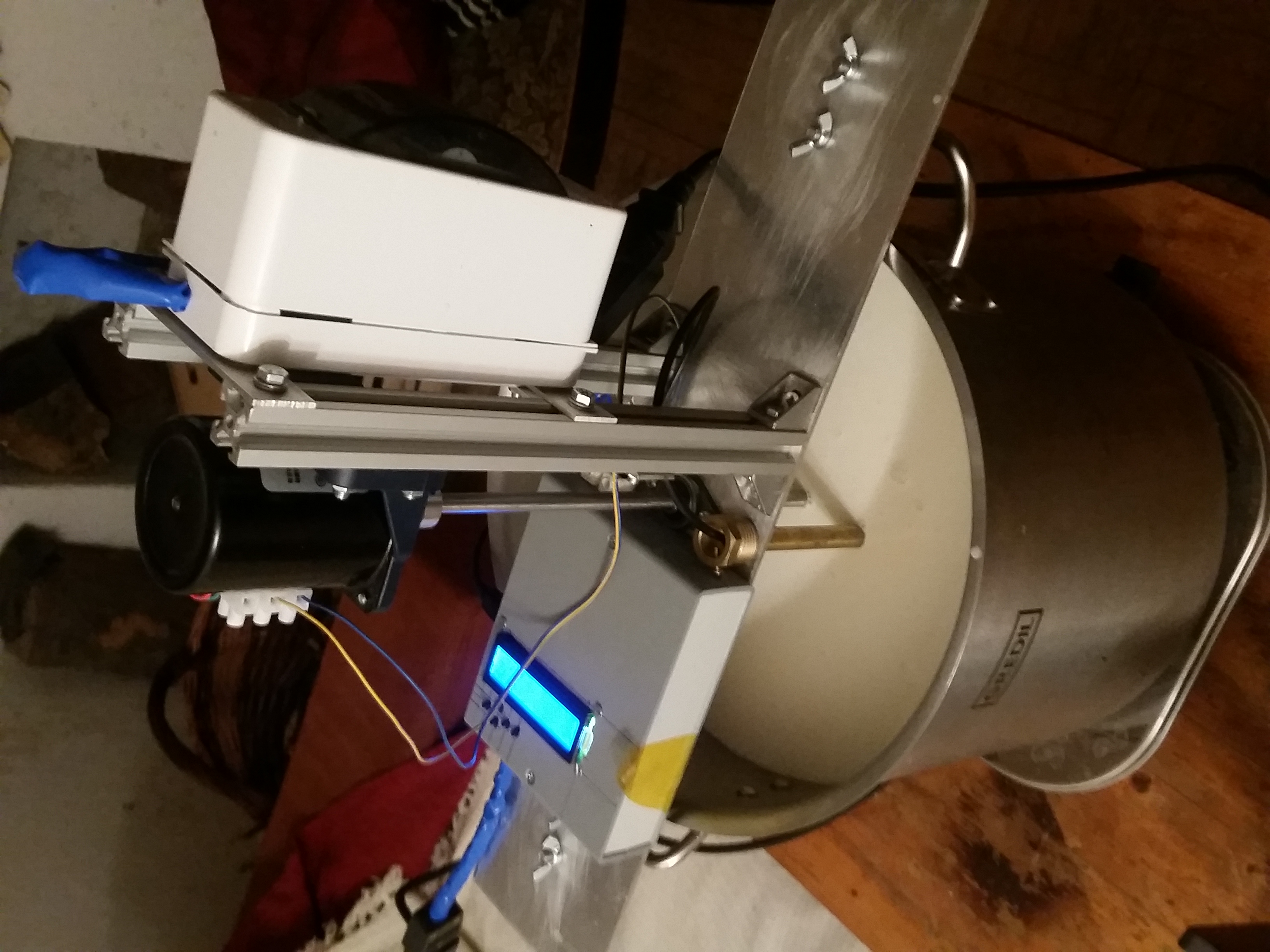
This device performs heating control using the PID method (proportional / integral / derivative) and control stirring (on/off).
Curd cutting has to be performed by hand but there are several methods envisioned to expand the prototype into making this process automated.
Vessel used is a 15L Gredil brand stainless steel pan.
1.1 Heating control.
Using a standard 1200W kitchen hotplate that has been wired to be controlled by an SSR relay (fotek brand) and a PWM signal, heating duty cycle can be defined by the
PID algorithm.
- Heating phase uses open loop control with inputted estimations of thermodynamic parameters (vessel geometry, external temperature, quantity of milk, heat capacity & transfer terms)
- Heat transfer terms take into account conductive and convective effects.
Due to the large mass of the heating plate, thermal inertia is quite high and has to be compensated with a large derivative parameter in the PID controller loop.
Ceramic is a good choice, induction plates even better, although there are few single plate portable models for these technologies. Price tag is higher.
Closed loop control kicks-in at a defined set point before reaching temperature hold plateau to minimize temperature overshoot.
A thermoter probe well is present and secured to the base plate to perform temperature measurement as close as possible to the project center of mass of the liquid to be heated.
1.2 Stirring.
A 28W low rpm single phase AC motor, geared for 15 rpm, provides enough torque to enable consistent stirring. The motor is coupled to a 8mm shaft, ending with two perforated 12*15 cm , 2mm wide 308 stainless steel plates, with each having 5 33mm diameter holes. the shaft is terminated on its contact point on the steel pan with a conical taper to reduce friction between the two. The shaft is secured by a standard 8mm flanged bearing to the base plate crossbar.
Not included in this prototype, but highly recommended is to provide a rotor lock detection mechanism by monitoring the current drawn by the motor, and disabling it in case of overcurrent. Monitoring the motor temperature is also recommended based on the provided datasheet parameters.
1.3 Protection and conformity devices.
The devices uses two DIN circuit breaker inside a 2 breaker box. one 10A for the hot plate power, one 2A for motor and Arduino power. the circuit breaker box is secured by screws to mounting struts across the two slotted aluminum profiles, earthing of the whole metallic chassis of the device is provided at this point.
Note that fast period PWM induces switching noise on the mains AC. An adequate line filter for a 1200W hot plate is recommended.
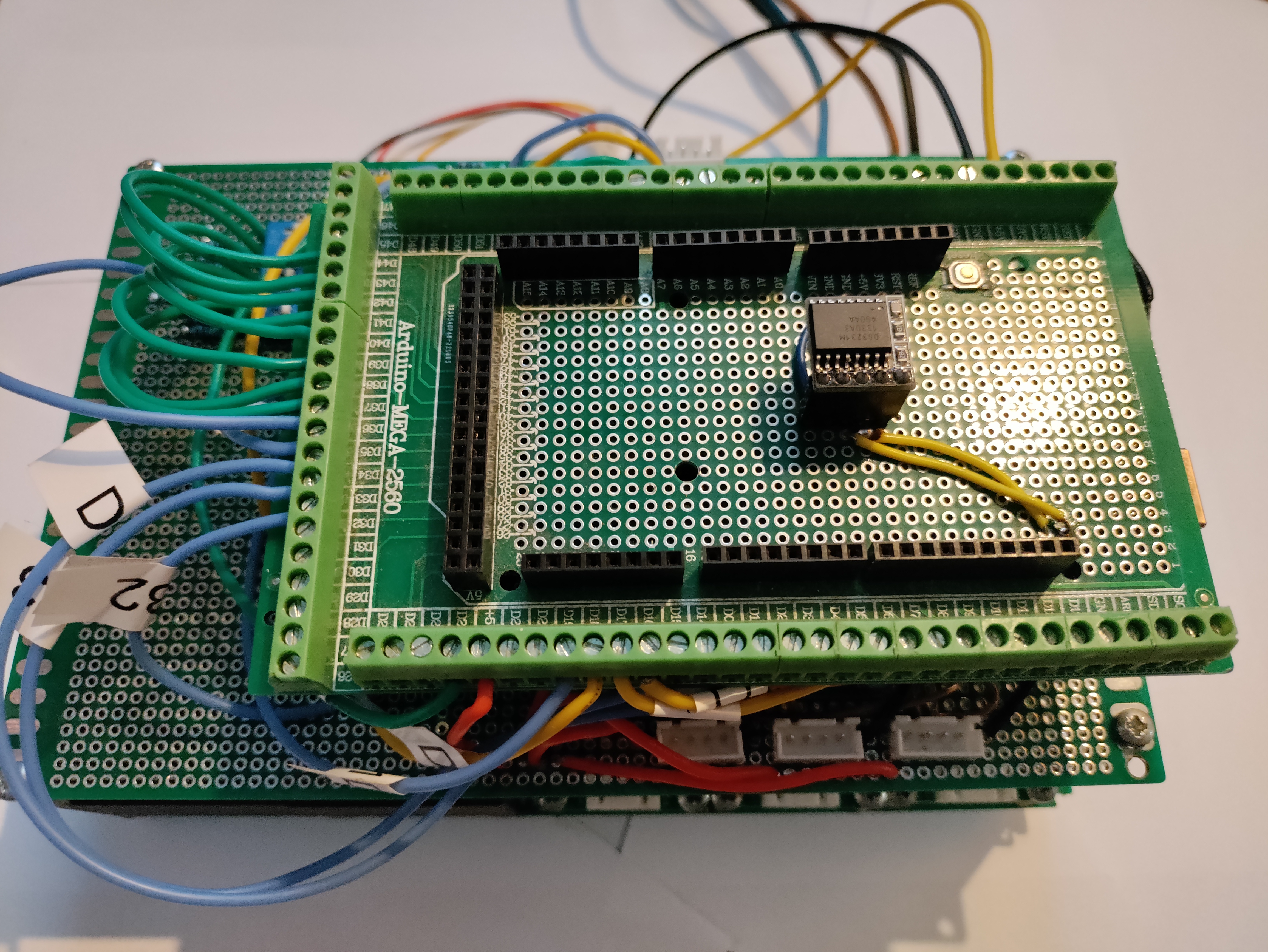
1.4 The controller.
An Arduino Mega 2560 with an LCD 1602 keypad shield is used to perform the following operations :
-Motor on-off control for stirring and hot plate PWM control
-Temperature measurement
-Liquid quantity measurement using a laser distance measurement module.
-User interface (LCD 1602 keypad shield) to input program parameters and program selection
Liquid quantity measurement is tricky and one need to carefully plan the placement of the module based on the datasheet recommendations.
Specifically, the hole through through the baseplate and electronics enclosure has to be wide enough not to disturb the laser cone, and it is also very important that the PMMA protection window is mounted as close as possible to the module, ideally in contact with it. A distance larger than a couple of mm is sufficient to induce large crosstalk, making the measurements lose precision. at 10mm distance, measure is no more effective. The placement of the module on the horizontal plane also has to be made distant enough to the vessel walls for the same reasons. Two more constraints : the protection window has to be thin and provide adequate IR transmittance. PMMA is a good choice. Also, water vapor condensation is a problem for hot running measurements. A hydrophobic treatment of the PMMA window is therefore required.
On the other hand, milk is quite reflective and allows rather precise measurement to a 5% to 10% error margin.
This module requires quite a lengthy process of calibration : distance offset, measurement of materials with different reflectance, and crosstalk calibration.
A simpler approach would simply to ask the user to input the quantity of milk present inside the vessel.
2. Bill of Materials.
- Aluminum strip 30mm x 2mm (for struts between the aluminum profiles, and to secure the breaker box) 50 cm
- slotted 20×20 aluminum profile, length depending on the vessel depth, and adaptability for varying depth vessels qty 1
- 68KTYZ motor, 10 rpm qty 1
- 68KTYZ right angle mounting bracket qty 1
- 8mm 303 stainless steel shaft, length depending on the vessel depth, and possibility of using vessels of varying depths qty 1
- 8mm ball bearing with mounting holes, model KFL08 qty 1
- aluminum shaft D19L25 coupling nut 7mm to 8mm qty 1
- stainless steel 309 plate, 12x30cm 2mm width. This depends on the vessel geometry. used for both paddle wings qty 1
- slotted profile 20×20 nuts, to secure struts, motor bracket, and plate to profile mounting brackets qty 12
- aluminum profile 20×20 90° corner brackets, to secure aluminum profile to baseplate qty 4
- ABS electronics enclosure 140x110x35mm Gainta Brand G738 qty 1
- thermometer probe on cable DS18B20 qty 1
- thermometer well, 20 cm length, 11mm width qty 1 2 DIN breaker wall mounting box (PawBol C.2030) qty 1 Arduino mega 2560 qty 1
- perfboard (at least 140×110 mm) qty 1
- LCD 1602 Arduino keypad shield qty 1
- laser time of flight (distance measurement) module TOF050C (VL6180X based) qty 1
- standard 5V relay module qty 1
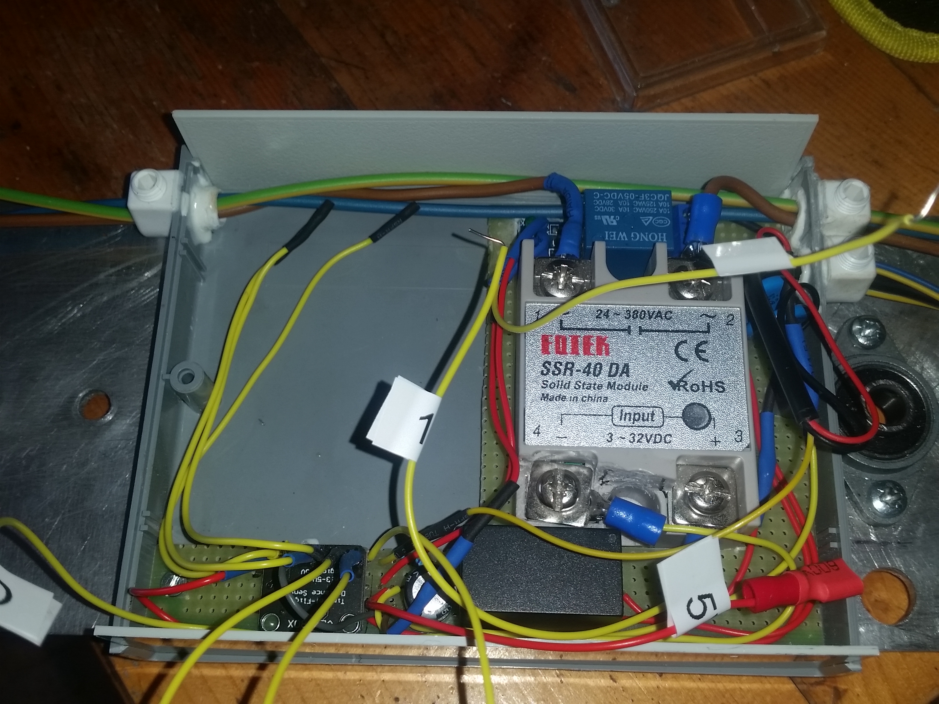
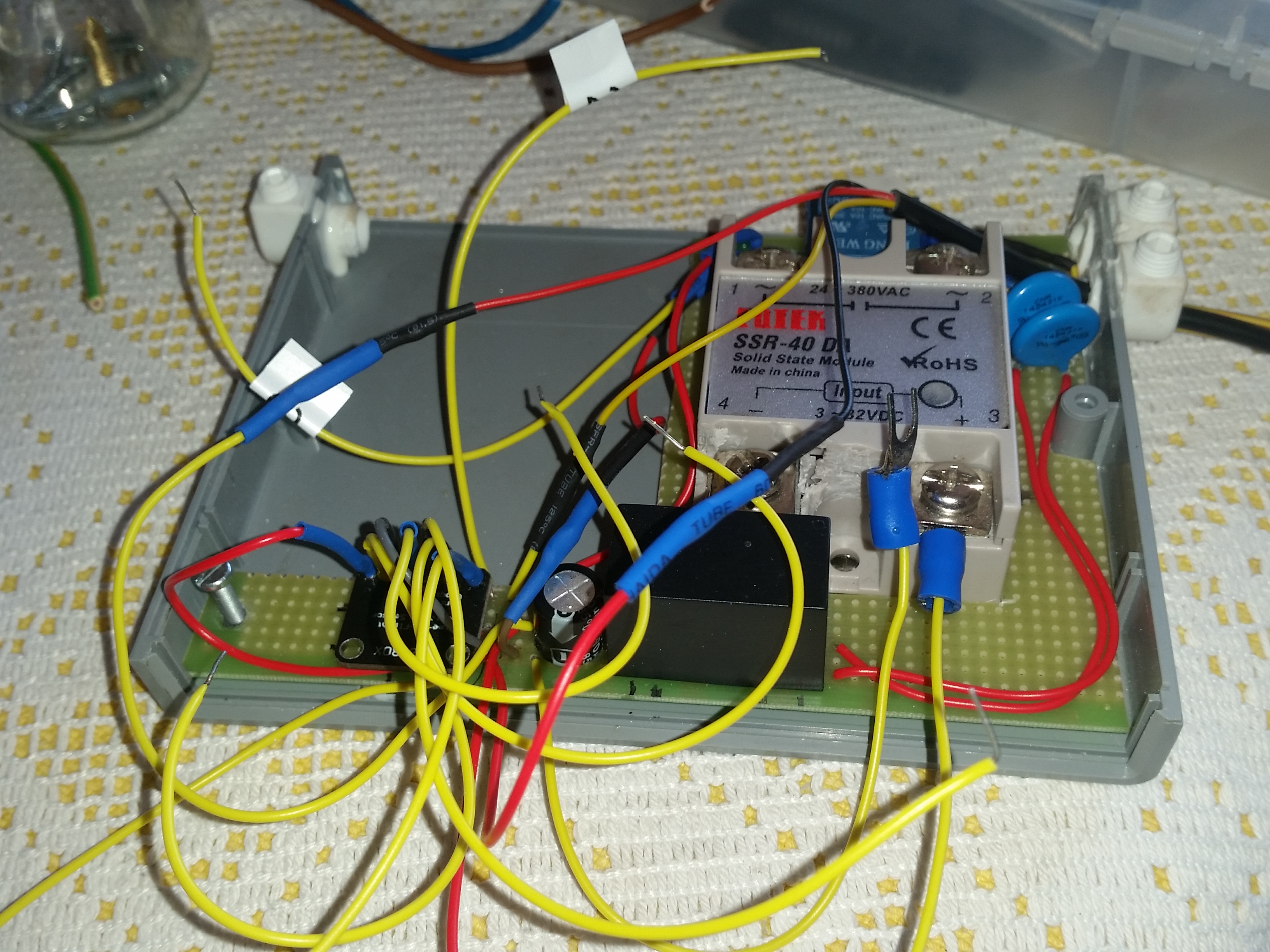
- Fotek SSR40DA solid state relay (5V DC control) qty 1
- Hi-Link 5V power supply module, 3W qty 1
- 275V varistor qty 1
- 4.7K resistor (for temperature probe) qty 1
- Silicon wire hookup cable, 22AWG qty 1
- M2,M4 and M5 screws qty 1
- IEC C14 male cable connectors qty 2
- IEC C14 female connector qty 1
- schuko cable C14 female terminated qty 1
- 1.5mm2 conductors, blue, brown and green/yellow, 1m
- cable relief and clamp nuts (for cables entering the electronics enclosure) qty 3
- 1200W hotplate qty 1
- 15L stainless steel vat, Gredil brand qty 1
- U bolts. geometry will depend on the stainless steel vat handles position qty 2
- butterfly bolts to secure U bolts to the baseplate qty 4
3. Tools needed
- bench drill and HSS metal drills up to 12mm diameter
- angle grinder with cutting disk and grinding disks
- drilling and cutting oil
- threading taps
- 33mm hole saw for metal
- stainless steel 2mm stick welding electrodes
- stick welding inverter
- perforated welding table or at least two vices, with one vice with XY axis regulation
- spacers of varying widths to assist in vertical position of the paddle during welding
- piece of copper to use as heat sink for stainless steel welding (to prevent warping)
- a dremel with 28mm cutting disks and small abrasive (diamond) milling bits with various forms
- soldering iron
- multimeter
- power screwdriver and angle grinder (to make the conical taper at the end of the shaft) or better, a lathe.
- caliper and measuring tools
- sharpie pen
4 Making the prototype
4.1 preparation of the baseplate
clean it and remove any protective film. mark the center with a sharpie. this will be the hole for the shaft.
drill the shaft hole some 20% larger so that there is leeway in final positioning of the shaft and bearing assembly
4.2 mounting the aluminum 20×20 profile
cut your aluminum profile in two parts (if applicable). the original extremities will be positioned over the baseplate,
since it is not certain that your cut angle is perfectly perpendicular if done with an angle grinder or a hand saw.
4.3 mounting the motor 90° bracket
place all T slot nuts inside the profile and position them for screwing the bracket. ensure that the base of the motor bracket is
parallel to the baseplate during test positioning. Screw the 68KTYZ motor to the bracket, install the shaft coupler, pass the shaft through
the bearing, position once again the assembly to the baseplate passing the shaft through the baseplate hole. test for shaft perpendicularity
using a protractor and you eyeballing abilities, using a protractor oriented in X then Y axis. beware of parallax. Note that this is not critical
since shaft coupling nuts have a helical groove to allow precession of the shaft, but it’s better to have the habit to do the right thing.
mark with a sharpie the outline of the corner brackets of the profile/motor assembly and the center of the holes of the brackets and shaft.
Check that the shaft does not contact the baseplate hole.
drill the holes for the baseplate to profile L brackets, again a bit larger so there is leeway for final positioning and screwing. once drilled secure the baseplate to the profile/motor assembly while checking that the assembly sits so that the shaft is perpendicular to the baseplate, again use protractor or a fancy laser. also at this point position the baseplate so the
shaft comes into contact at the center of the vessel bottom.
4.4 U-bolt baseplate to vessel fasteners
At this point it’s time to prepare the u-bolt holes that will be used to secure the whole device to the vessel using its handles.
this part is critical.
mark the contact point of the vessel lid to the baseplates, 4 points in total. will be useful if it moves inadvertently.
Since there is no contact except at the lid of the vessel, you’ll need to use a square ruler with a large contact area to project the handle of the vessel to the baseplate, offset to the centerline (axial) of the handle cylinder, and add offset of half the distance center to center of the u-bolt, mark the holes and drill. better drill to exact u-bolt bolt body dimensions, so there is no room for it wiggle if the butterfly bolts come loose during operation.
once again unscrew the motor/profile assembly and remove the shaft, and drill the u-bolt holes.
after that repeat the positioning steps above with the motor/profile assembly on the baseplate secured, and the baseplate secured to the vessel using u-bolts and check that
the shaft once again contacts the center of the vessel.
4.5 layout of thermometer well and electronics enclosure
test layout of the remaining components all at the same time :
the thermometer well, the bearing orientation, and the electronics enclosure.
there is a constraint on the VL6180X laser distance sensor (the laser cone of avoidance). some trigonometry will be helpful to define the minimum diameter of the electronics
enclosure window and the baseplate window. verify that the cone divergence does not intersect the wall of the vessel.
you can also skip this part because it is quite tricky and go for static liquid quantity input by the user.
4.6 securing the ball bearing to the baseplate
mark the holes for the ball bearing while the motor/profile assembly is correctly positioned.
remove the assembly again
secure the ball bearing. position and secure the motor profile assembly again, check that the shaft does not contact the baseplate.
4.7 thermometer well installation.
you can either place the thermometer well in the hole, it will rest on its flange, (quick and dirty) or glue a NFT threaded adapter to the baseplate so you can screw in the well and it does not move. you’ll have to carve out a slot in the paddles so that the well does not collide with the rotating paddles
4.8 define the layout for the components inside the electronics enclosure
at this point you should have the positioning constraint for the distance laser module on the XY axis.
non soldered components are the SSR and motor relay : they will be freestanding inside the enclosure and secured by the perfboard on their sides
the Arduino and LCD shield assembly will be secured to the top part of the enclosure.
Drill two holes in the perfboard at least, diagonally, you’ll use the same screws to secure the perfboard to the enclosure and to the baseplate.
position and mark baseplate with a sharpie through the bottom cover holes.
Drill the baseplate holes. baseplate holes maybe threaded or not and you’ll use bolts. it’s up to you. I tapped threads and was lucky. beware that threads in aluminum are soft compared to steel. threading is less robust but a little more elegant than bolting.
test mount bottom cover and perfboard to the baseplate.
Carve out the perfboard for SSR, relay and Arduino footprints. This step is required if you use the enclosure specified (Gainta) since there is not enough space on the Z axis for these components. if you find a better enclosure on the market, lucky you ! or just 3D print one.
The good side of the tightness of placing was that the perfboard maintained the two relays in place. better carve out less so that you finish with a
mill bit on the dremel and obtain a tight grip of the perfboard to the components.
also note that I had to chop parts of the fotek SSR plastic near the connecting terminals to connect the washer type electrical connectors.
of course, before carving out, you have to make sure that the remaining components fit on the little perfboard you have left : that is, the varistor on the AC side, power module, and the thermometer module resistors, maybe an electrolytic capacitor on the PSU output.
4.9 remaining holes on the bottom part of the enclosure
the bottom part of the enclosure will have three additional holes for the wire ports, two at the side closer to the center of the device :
one for the hot plate electrical wiring input to the enclosure (phase, neutral, and ground) the other port for the stirring motor power output (AC), and the MCU + motor power input (AC)
the distal hole from the center is for power output going to the plate.
If you have a precision bench drill use it for the holes in the enclosure, and finish with a dremel when required. the port holes are better milled with the dremel, since there is usually no
clearance to drill them with a precision bench drill, unless your setup allow to do so.
so, to sum up, the enclosure bottom part has these holes :
2 mounting holes to secure to baseplate and perfboard
3 holes for cable routing
finally, one of the enclosure plastic insert sides should have a hole for the arduino USB connector.
4.10 Soldering the components to the perfboard
First, A note about the VL6180X module
if you decide to implement it, remember that the PMMA window has to :
- make the enclosure airtight and watertight
- be in contact with the module itself to lower crosstalk to a minimum
- be fog treated
- be heat resistant. better measure the temperature at that point at the maximum operating temperature and liquid quantity of the device. 92°C liquid temperature is used for milk sterilization
that means that the Z axis section for the laser module has to be layered as this (going downwards) :
- perfboard
- laser module (using 90° header pins)
- pmma window
- enclosure bottom cover
- baseplate
the PMMA window should be way larger than the hole so that the epoxy gluing step does not smear glue down the hole. use the least amount of glue over a rectangular path,
so the enclosure stays airtight.
Remember step 5 and check underside that the VL6180X chip is well inside its positioning margin so that the laser cone does not interfere with any part. re-mill if needed.
better perform calibration before gluing the window. the process is outside of the scope but there are well documented in the datasheet. You’ll have to write into quite a lot of registers.
on the VL6180X, check my code (will comment it better soon)
Also the module will be soldered on the perfboard bottom layer. a dual layer perfboard is thus required.
Finally, the perfboard may not be in contact with the bottom of the enclosure because of the module, in the case you do not use the provided mounting holes on the enclosure, as they provide some clearance from the bottom cover. if I remember well, I could not use them because of the crowded layout. This may lead to the bending of the perfboard, and axial force on the perfboard/cover/baseplate screws. if you manage to add plastic standoffs washers over the screws between the perfboard and the bottom cover, it will give a better result.
4.11 wire soldering to the perfboard (perfboard to perfboard and perfboard to freestanding)
pass the DS18B20 wires inside the wire restrain port and solder them to the perfboard.
solder the AC carrying wires leads (low amperage, these will connect to the 2A breaker and supply power to the module and motor) to the varistor and pass them through the port, later they will be bundled with the hotplate carrying wires. this could lead however to stronger switching noise coupling from the PWM operation to the AC power lines to the controller and motor.
In my case I did not use any line filter in the enclosure since there was no room left, but the hi-link module probably handled this well as controller operation is stable.
solder the hi-link power supply, and all interconnect wires.
this project feeds 5V to the Arduino through the 5V pin, so it bypasses the regulator, thus an electrolytic capacitor is advised to smooth DC when the motor relays kick in.
hi-link power supplies are good if you get the real thing, mine had to be opened, and a soldered wire was loose so it didn ot supply 5V. either i did not have luck or it was
counterfeit crap. lucky that it was just a wire issue. Always test ‘complex’ modules and components on breadboard first ! and if you can, order more than required since they’re cheap
and take time to get to you. Always think about logistics in any project !
One more advice :
I made the rookie mistake to use single stranded breadboard wires. don’t do that, they are fragile as f*** and break on torsion. used proper multistranded hookup wire.
label all the hookup wires on the perfboard side with a Dymo.
secure for the final time (hopefully) the perfboard, bottom cover, and baseplate together.
put the Fotek SSR and the relay in their designated perfboard placeholders
additional internal wiring using DuPont connectors are 5V,GND,relay logic for the motor relay, SSR relay logic and SSR DC ground.
the Chinese 5V relay modules provide male header pins. I advise not to directly solder hookup wires since that will make any servicing difficult.
Fotek SSR use large screw terminals the like used on overcurrent protection breakers, you’ll have to use washer type electrical connectors.
4.12 hot plate power power wiring
Pull neutral and ground 1.5mm2 wire through the enclosure through one of the ports on one side, across the enclosure, to the exit port.
split the same length of brown phase wire in two and solder a washer type electrical connector on one end of each wire, connect them to the AC part of the Fotek SSR.
the connectors will connect one one side to the dual pole 10A breaker on one side, and to the female (important that you use Schuko IEC C14 female connector here to prevent electrocution from the potentially energized prongs when it is disconnected from the plate) Schuko connector that will connect to the male ended Schuko connector cable going to the hot plate.
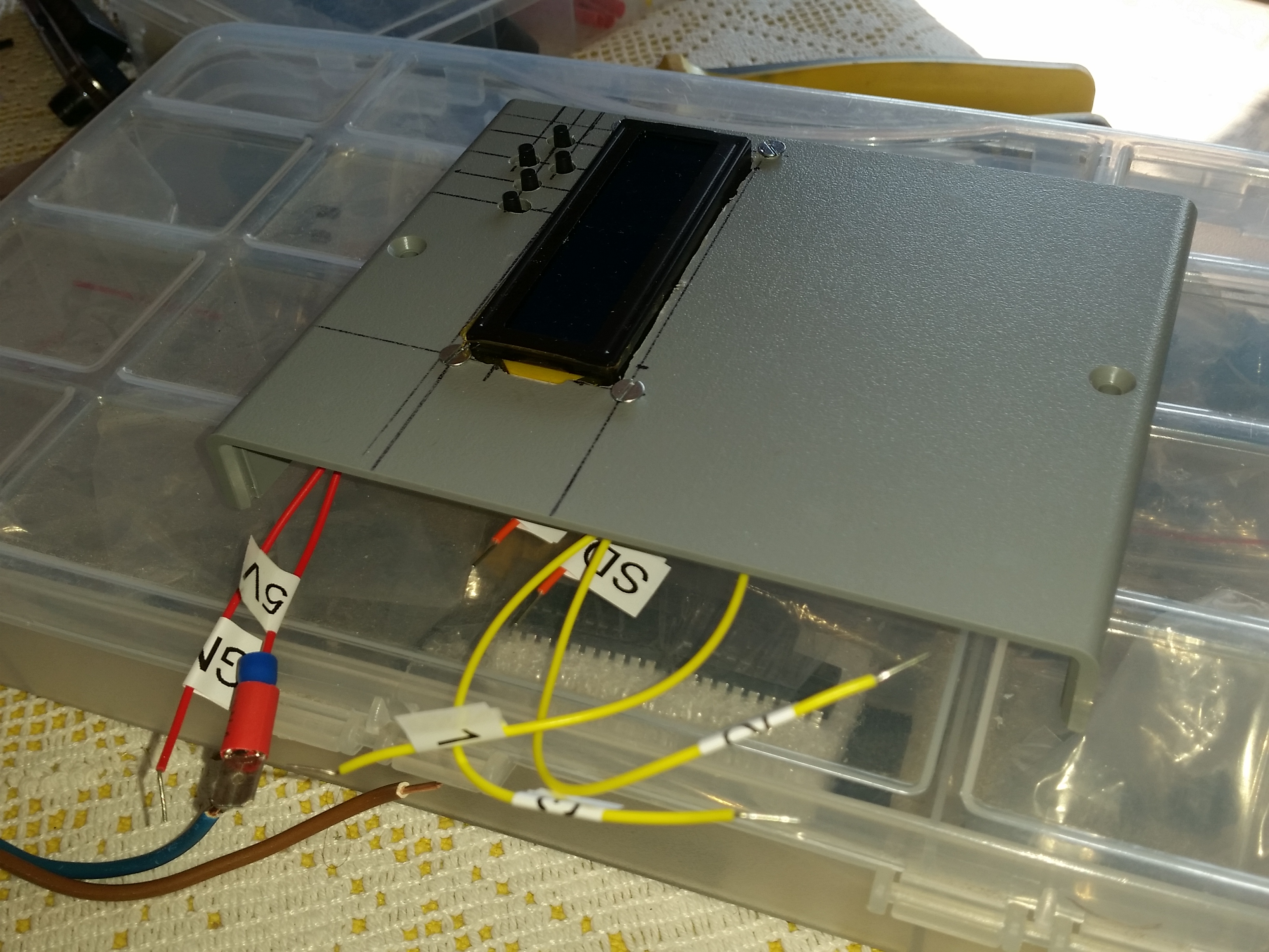
4.13 prepare the Arduino and the LCD 1602 shield
unfortunately the LCD 1602 shield pin headers come into contact with the top cover in my configuration. the easiest way for me was to saw them off with the dremel.
take care to not let drop the shavings mindlessly.
next solder hookup wires to the LCD shield for :
- DS18B20 data
- SSR relay logic
- motor relay logic
- 5V
- GND
And if you use the I2C VL6180X laser distance module, add these cable leads (that’s because the LCD1602 keypad does not route the SDA/SCL through its pins, what a shame) :
- SDA
- SCL
4.14 prepare the top part of the enclosure
The fact that the LCD keypad shield plus Arduino have to be secured to the top part of the cover introduces a severe constraint for wiring the whole project.
That’s all Aliexpress had to offer in 2022.
This whole part will have to be rethought in any next iteration, with ideally an LCD keypad solution with ribbon cables and board to board JST connectors, and a PCB plus embedded Arduino on the bottom part, and a larger enclosure on the Z axis.
The top part will have a carved out rectangle for the LCD display, 4 holes to secure the Arduino/LCD and 5 holes for the keypad buttons,
Mill an opening on the enclosure top cover for the LCD1602 display and the five buttons keypad, with the dremel using cutting disks for the opening and milling bits for the keypad. you’ll also need mounting holes, beware when milling there is very little clearance between the holes and the display opening. go slow.
finally connect the shield to the Arduino and mount the Arduino with the shield to the top cover. screws and nuts required.
4.15 connecting the hookup wires leads from the Arduino to the wire leads going to the perfboard, the SSR, and the relay.
put a heat shrink tubing section on the cable solder all hookup wires from the perfboard / relays to the corresponding hookup wires of the Arduino/LCD, place the heat shrink tube over the solder and apply heat.
Of course, for this part you can go for ease of maintenance and just use DuPont male to female connectors cables to connect the bottom cover components to the Arduino, I just trust them less in the long term.
This part is a bit cumbersome since it has to be done with the enclosure partially closed, just to expose the wires.
4.16 closing the enclosure
once everything is in place close the enclosure slowly, checking not to pinch any cable, and screw and tighten the top cover.
4.17 circuit breaker box installation.
While one side of the parallel two 20×20 profiles is used for the motor and its bracket,
the other side will be populated by the electrical breaker box. I used a model for two DIN breakers, since I’m in Europe.
the box will be mounted on the two aluminum strips that serve also as struts. I made two diagonal holes to secure the box, one of these holes will also be used to ground
the device chassis, by the means of a washer electrical connector. grounding for the hot plate has to be provided, so you will need a 3P Wago to extend the earth or use two washer
connectors on the grounding point.
functional tests of the completed device will be covered in another post.
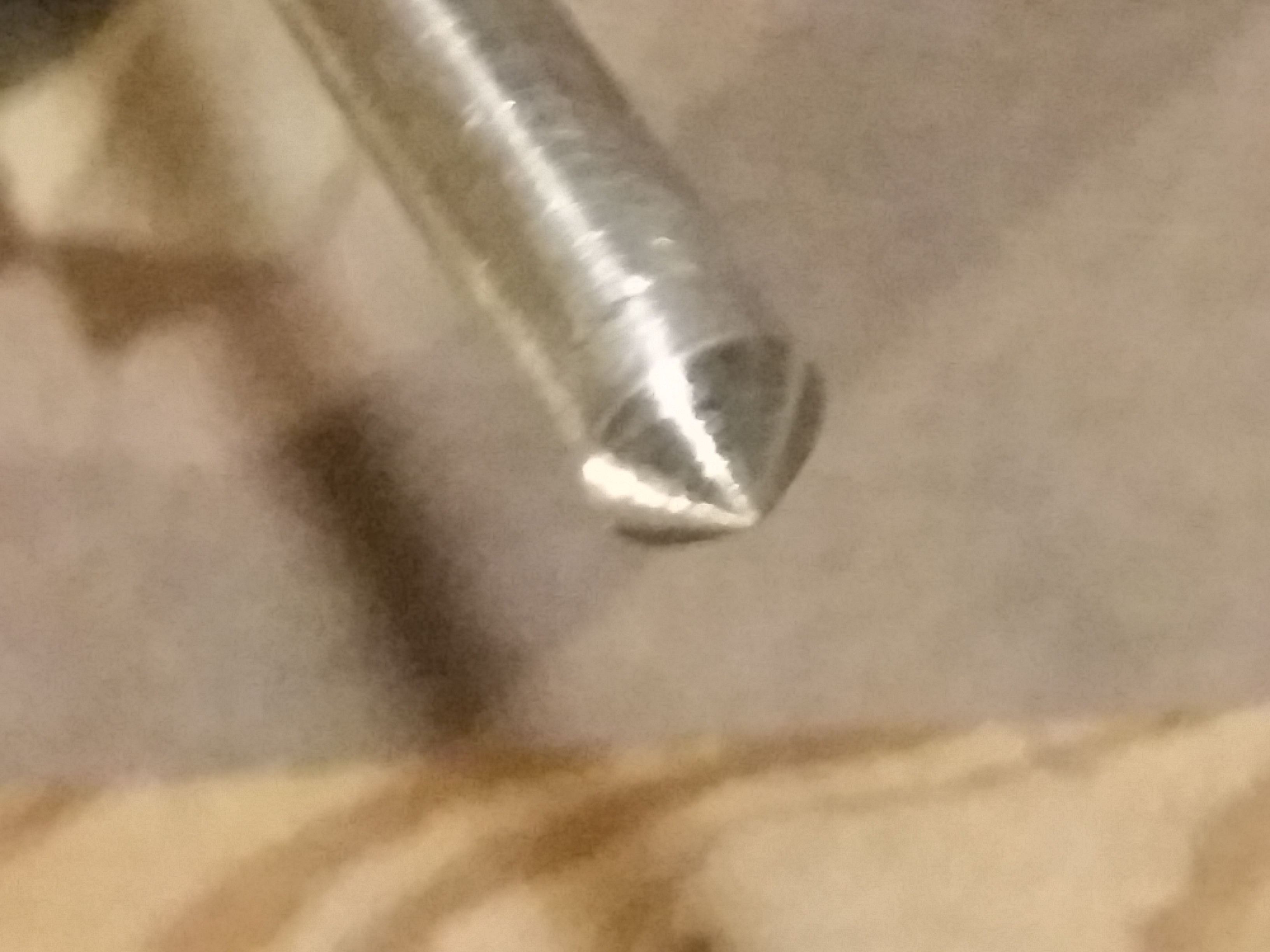
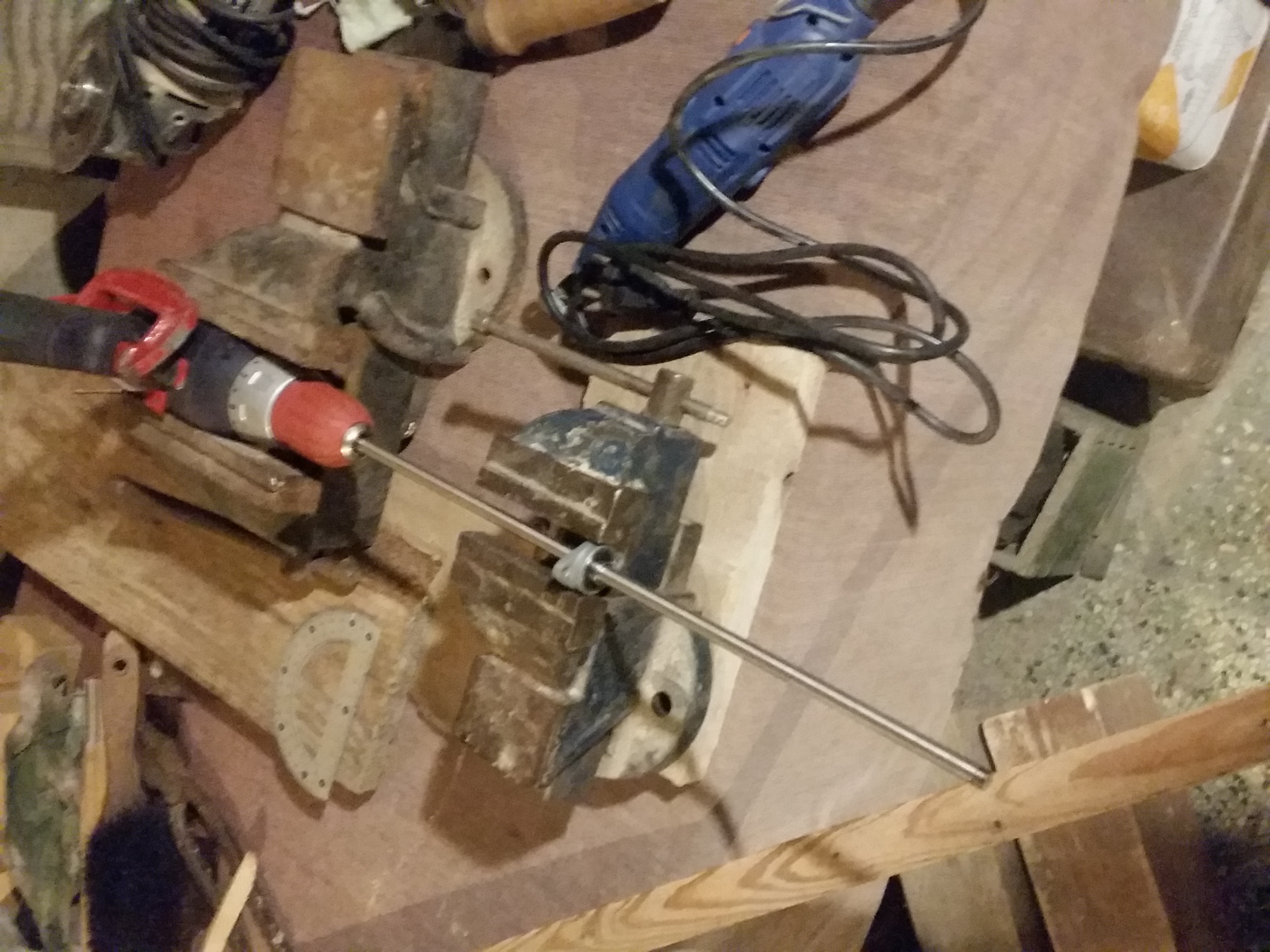
4.18 shaft conical taper
use a lathe or if you haven’t any, make the shaft spin on a power screwdriver, with support along the axis with a ball bearing secured on a vice.
have someone assist you or clamp the power driver trigger so it spins without assistance. once the shaft spins, make the conical taper using the angle grinder.
4.19 paddle cutting and perforation
using a metal hole saw, drill the holes on each paddle, using the same layout for both paddles. check the CAD model.
use plenty of drilling oil and stop drilling and let the saw cool down if smoke appears.
4.20 paddle welding
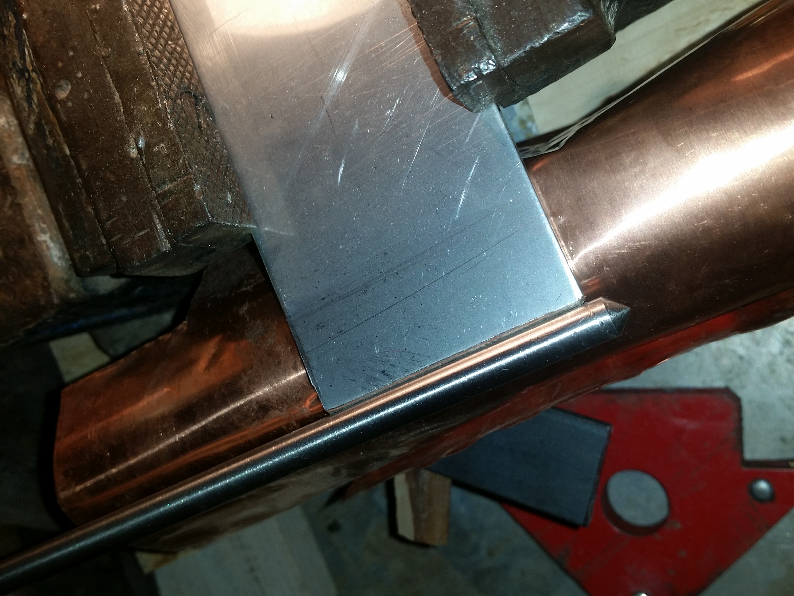
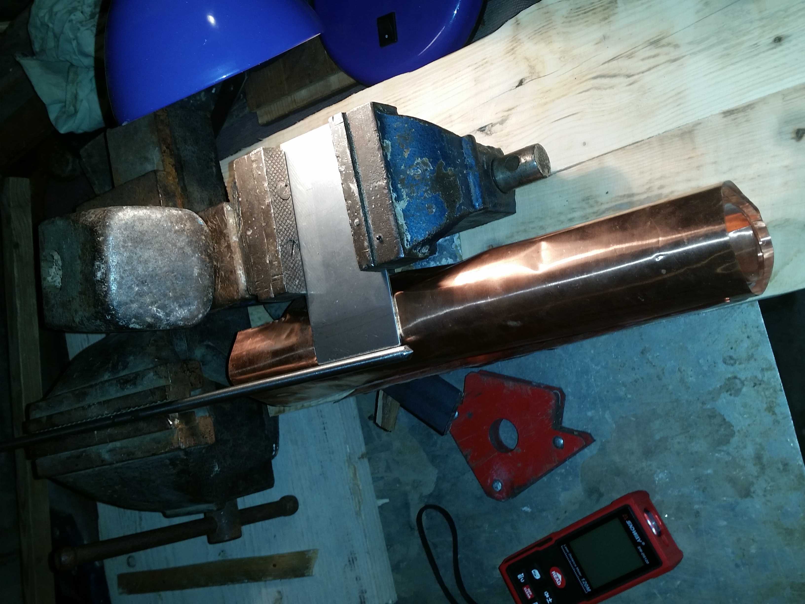
This part is tricky, because the fixture is a bit complicated to make when you don’t have the proper tools. Best is to have a true welding table with different types of clamps. If you have no welding experience, better give the work to a welding shop.
Without adequate tools you can make a somewhat ok-ish fixture using one vice to secure the shaft, and another 2 axis vice. you will need some spacers placed under the vice to adjust the them on the vertical axis relative to one another, so that the paddle width centerline is aligned diametrically to the shaft.
Then adjust XY axis on the vice that hold the paddle, just above the conical taper. better to have some margin if the paddle ends misplaced so that it does not contact
the vessel when you’ll test it, it will spare you some grinding. in my case, i ended with a max. 5mm margin between the paddles and the vessel, on the base and on the side.
If you’re a beginner like me, it should work (not ruining the parts) but aesthetically it could be crap.
I made a 45° bevel on both sides of the edge to be welded to create a groove to improve the weld robustness.
not sure if it really helped though, better ask a professional.
I used 2.8mm 308 stainless steel rods at 80A, I think it is a bit too hot, but I don’t know if my crap welder is calibrated for amp measurement.
The most important thing is a precise alignment of the paddle to the shaft and to use one or two copper heat sinks contacting both the paddle and the shaft close to the
weld area, underside of course. even like that, the shaft may warp. do not be too alarmed if it does though, because when welding the reverse side, the warping will revert, but because of this you could have trouble to make precise contact to the copper heat sink though.
repeat for the other paddle.
I learned that stainless steel welds may need passivation or electropolishing after welding to be fully corrosion resistant. there are DIY electropolishing methods involving strong acids like phosphoric acid and current, passed through some mineral fiber soaked in acid, and connected to an electrode. check Youtube.
4.21 final paddle assembly rotation tests
make free wheel shaft/paddles spinning tests with the motor coupling Allen nuts loose. it should not contact the vessel sides or bottom. A final test will be required with the motor on.
upload a test firmware to the Arduino and test the relays. at this point the motor relay is the focus of our attention, make the paddle spin, and if it contacts the vessel, grind the paddles at the point of contact until they no longer do.
4.22 breaker box to enclosure wiring connection, enclosure to motor wiring connection, enclosure to hotplate wiring connection, breaker box to main AC input connection
To sum up, there are three bundle of cables : phase, neutral, protective earth for the hot plate, passing through the enclosure and going to the 10A breaker, plus phase and neutral going to the 2A breaker. (since there is no line filter the protective earth does not need to be routed to the controller enclosure) these will provide power to the controller and to the motor through the relay.
and finally a bundle of cables exiting the other side is going from the enclosure to the hotplate.
the lone remaining cable is for the DS18B20 probe and will be shoved down the thermometer well.
use shrink tubing over each bundle and hot air gun blast it. then pass the leads down the breaker box hole on the top and connect them to the respective breakers.
do the same for the enclosure to hotplate, with a Schuko IEC C14 female termination. since the hotplate has to be easily disconnect from the rest, that’s why we terminate we a Schuko. keep this cable and Schuko connector length short.
Screw Schuko connectors are a bit tricky to fasten properly, in my opinion. If I had to do it again I would sacrifice a power cable to use the molded connectors.
repeat the process for the main power AC input, use a male IEC C14 Schuko this time. this cable enters the breaker box through the bottom. keep this cable and Schuko connector length short.
5. Additional resources.
5.1 Firmware
Firmware is available at https://www.github.com/rodv92/milk_heater2
Alpha Version.
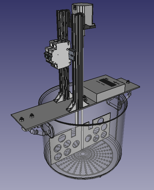
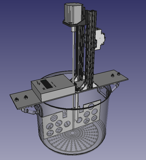
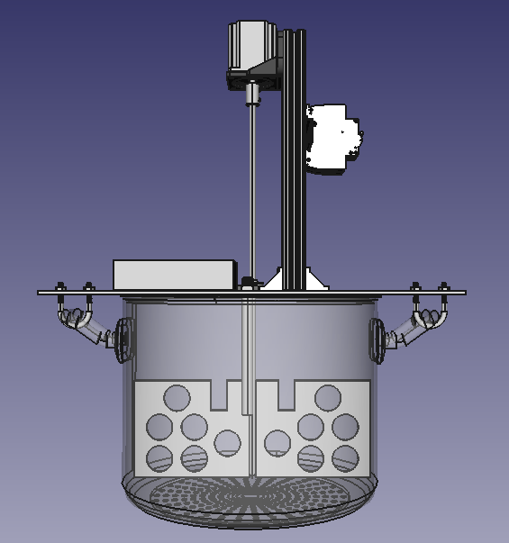
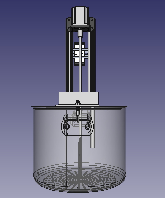
5.2 CAD model
Take the model with a grain of salt. it’s mainly for illustration purposes and I used available GrabCAD and Mc Master Carr parts models, some of them do not match the components I’ll used.
the model, as for the date of this post, lacks drilling information, the breaker box is also not modelled.
If one day we have an AI managed database of all market available solid parts, using 3D reconstruction, that will make modelling easier, but human modelers will be rendered obsolete.
AI will drive one of the largest work shifts in human history, that’s for sure.
CAD model uses FreeCAD v 0.2 the model is available in :
https://github.com/rodv92/MILK_HEATER2/tree/main/hw
5.3 Schematics
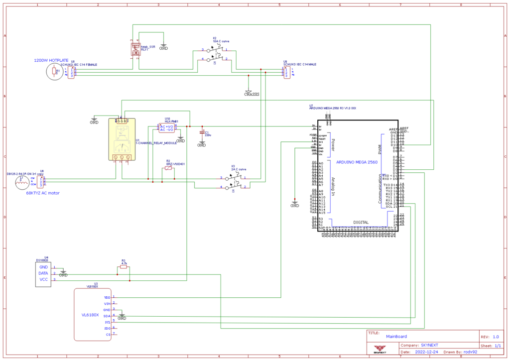
Also available at (authoritative resources are uploaded on GitHub) :
https://github.com/rodv92/MILK_HEATER2/tree/main/hw/
5.4 Pictures

I hope to keep this project alive so It may serve the makers community well.

)